|
|
CAN-Bus 9 (errors)
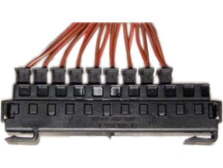
| CAN-Bus-distribution (Mercedes) |
| Manufacturer-workshop testers have a definite advantage. |
That which interests us the most with the CAN-Bus is of course the fault finding. This is comfortable when applying a workshop (manufacturers) tester, where the software for this CAN-Bus is fitting to the message
codes, and stays that way through regular updating. It recognises the no longer available subscribers when both data-links are blocked. Mostly, it helps to lay the intact link on the mass, so that it it can point out
precisely the part of the Bus which is defective, thus making it easier to limit the error-area.
| Disconnect individual subscribers and observe the Bus. |
It's nice if you can also do your testing with it. However, if such a device is not at your disposal, there are other possibilities to localise the error. If we assume that the bus is disturbed at a certain point, disconnecting the
leads and thus, the individual subscribers, does make sense. At the same time, one can observe and determine through a
function test, the tester, the oscilloscope and even with a multimeter, when it's working again. It is important to plug the individual leads in again after each test.
| It's good to know, where everything is connected. |
To ensure, that in the event of a defect in the door-control device, one does not have to dismantle all four doors (maybe even five) one after the other, to know at which point (there may also be several) the individual
strand-cables are brought together. From there, one can comfortably disconnect individual cables, which may mean that one must only have to open one door from the inside. Whatever the case may be, a quick repair
of the remaining Bus is made possible.
| Through the voltage, the bus activity for CAN_H/CAN_L can be seperately recognised. |
By the way, when measuring with the multimeter, caution must be taken. When measuring the resistance, it is quite possible to destroy one or more subscribers. So, play it safe and stay with the voltage measurement.
Should one measure between the respective data-cable of the low-speed Bus and mass, one would recognise CAN_H by the 0 V and CAM_L by the 5 V, as long as no data transfer is taking place. Otherwise, the value
of CAN_H can rise to max. 1 V, whereby CAN_L drops minimally to 4 V. This is then, what an intact Bus would look like.
| A sensor failure can lead to a number of different reactions. |
The exemplary error analysis begins with the customer dialogue. One can ask e.g., which other functions fail at the same time as the appearance of the error. The customer often sees no connection, which is why it's
worthwhile to ask more exactly. Since the CAN-Bus supplies any number of control devices with information at the same time, if one fails it is certain to effect others, at the same time, it's a good tip to where the error
may be found. Now, whoever can read well structured plans and other data processing, may be able to trace the error, almost without measuring.
At the latest then, when the engine has a fast CAN-Bus, a fast oscilloscope must be used, which makes the data-blocks visible, right into the bit-area. Here there are also continous effective resistances at work, which
must be considered, e.g., when measuring with a multimeter. However, because you should assume incorrect- and not missing connections, you can best determine the voltage of CAN_H and CAN_L separately
against mass. 01/10
| High-speed Bus |
| Measured voltage | Error cause |
| Approx. 12 V | Contact with the on-board electrical system |
| Approx. 5 V | Contact to TTL-voltage |
| Approx. 2,5 V | No complaint |
| 0 V | Contact to mass |
|
|