 Electric Drive Technology 2 Electric Drive Technology 2
Electric powertrains in automobiles have transformed the automotive industry. Even our Hyundai Kona, a mini-SUV just over 4 meters long, has 150 kW (204 hp), not continuously, as with a combustion engine,
but when you accelerate, you can really feel it despite the heavier weight.
There was an Iveco truck with over 735 kW (1,000 hp), more than any diesel engine can generate. In the meantime, performance levels are falling again in favor of even greater cost-effectiveness, which is a
good thing. But it does show that power outputs of around 150 kW and a little more are standard in passenger cars.
We will now proceed on that assumption when considering the drive motor. This also applies to the transmission in a car with two stages, not two gears, mind you. The most commonly used motor today has
external electromagnets and a rotor with internal permanent magnets.
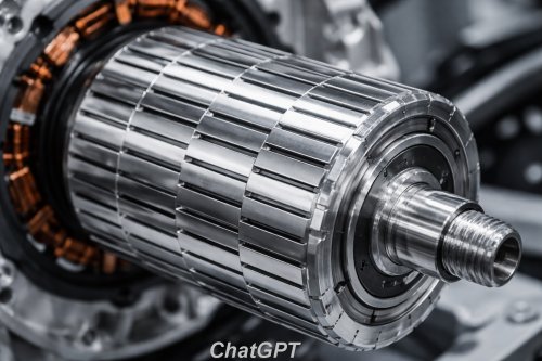
We have already mentioned the resolver on one side and the rotor output on the other. So let’s get right to the heart of the electric motor: the rotor. When you saw the picture above, did you think that a part
like this was made up of countless thin, individually insulated sheets?
This is known as lamination, and the reason is that in a closed metal block, eddy currents can spread due to the constant changes in the magnetic field, which leads to heating
and thus to lower efficiency.
By distributing the dipoles across different metal sheets, it becomes significantly more difficult for eddy currents to spread. The principle has been around for a long time. If you open up an old transformer, you’ll
also find a stack of metal laminations like this, though this time they're purely static.
So the losses will be smaller. They are slightly raised by offsetting the grooves relative to one another, which, as can be seen in the image above, were apparently cut
before the rotor was assembled. This prevents a phenomenon known as 'torque ripple'.
The longer the grooves in the stator are, the more they create a kind of resting moment due to the magnetic attraction between the grooves themselves and the magnets in the rotor; this phenomenon occurs
primarily at low speeds.
This results in jerky movements, vibrations, and even noises. In addition to the 'partial use' described above, an inclination is also possible. Apparently, the problem can also be addressed from the
software side.
We have already discussed and illustrated the arrangement of the magnets in the rotor in eDrive 1, in the chapter on reluctance motors. Let’s move on to the poles in the stator, six of which is still the smallest
number found in electric vehicle motors.
There can be up to 12. A pole pair consists of windings with the same polarity arranged side by side in the stator. Strictly speaking, 6 pole pairs also cause 6 changes in
this, but only the north-south cycles are counted, i.e., 3 (the number of field periods).
It is logical that, for example, when the stator is divided into six pole pairs, these are designed more for higher speed, whereas with eight pole pairs, they are designed more for torque. This would be very
important, for example, in an electric truck with an input gearbox for driving off.
Finally, a word about cooling. Not everyone invests as much effort as Tesla does in oil cooling using a pump and filter. A more ordinary design would be one driven, for example, by gears in the transmission, or
even simpler by water, with a two-part housing-partly featuring small cooling fins-that fits together and is welded.
|