 Electric Drive Technology 1 Electric Drive Technology 1
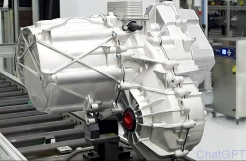
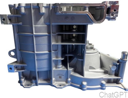
The most advanced design of an electric drive is also the most compact. In this design, the engine, mostly a single-speed transmission, and the differential are housed in a single casing. Above it sits the
inverter, connected to the motor both electrically and via two cooling lines.
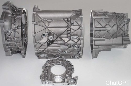
All housings are made of aluminum because of their light weight; many still weigh over 100 kg, but some weigh significantly less. Using the same material throughout ensures uniform thermal expansion,
thereby preventing the parts from warping relative to one another.
When disassembling the motor, the three terminals immediately catch the eye; they are usually just steel strips of sufficient cross-sectional area. However, there are also connections between the inverter and
the motor that consist of flexible cables.
The three-phase connection is, of course, the lifeline of the electric motor. Therefore, none of the three should come loose or come into contact with other conductive parts. Depending on its design, the engine
can often only be disassembled using very specialized tools.
Even without an electric current, the magnetic force between the stator and the rotor is often so strong that the rotor presses against one side, causing damage if it cannot be kept as far away as possible. The
narrow gap between the two presents an additional challenge.
The gearbox usually consists of two gear pairs, with a very small diameter on the drive side and a very large diameter on the other side. The width of the gears increases significantly in the direction of the force
flow and increasing torque.
That's because of the high gear ratio, which is well over 10. Electric motors rotate at about three to four times the speed of internal combustion engines. What follows is a surprisingly conventional differential.
More compact solutions using balance wheels instead of planetary gears have not yet gained widespread acceptance here.
The resolver is located on the other side of the rotor shaft. It has small excitation and measurement windings and can precisely determine the exact angle at which the rotor is currently positioned relative to the
stator or housing.
The converter in the inverter needs this to control the individual electromagnets in the stator at the right time. The resolver is available in adjustable or fixed versions. In this case, the software will automatically perform any
necessary readjustments over the course of its service life.
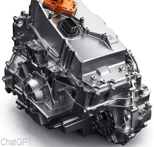
That is all that remains, the inverter, just like all the other components, housed in a sturdy casing. Somewhere here, inside this orange enclosure, the two cables from the high-voltage battery are terminated. Right at the
entrance, there is a filter to prevent the backlash of switching operations from affecting the battery line.
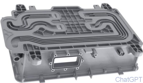
Next is a relatively large section for the capacitor. It’s probably designed for smoothing tasks, but it also absorbs energy during recuperation, for example, which can’t get into the battery not so fast. It doesn't necessarily
have to be very cold.
That must do just the next partition, the one with the switches for the individual phases. It is therefore possible that coolant flows through several areas,or just this one, and is then directed straight to the engine. Incidentally,
when it comes to the water circuit, leak-tightness is almost even more important than in an internal combustion engine.
So at least the transistors capable of handling high currents need to be cooled, and a measurement of these currents is also required. This sensor system is particularly important because it prevents, for example, errors
in the control system, as well as those between the stator and rotor.
|