|
| 
|
 Two-stroke engine 3 Two-stroke engine 3
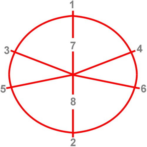
| 1 | Top dead center |
| 2 | Bottom dead center |
| 3 | Open overflow channels |
| 4 | Close overflow channels |
| 5 | Exhaust channel opens |
| 6 | Exhaust channel closes |
| 7 | Inlet |
| 8 | Exhaust |
This would be a typical symmetrical control diagram for a two-stroke engine working through in a clockwise direction. The exhaust channel is located higher in the cylinder than the overflow channels, so it opens earlier and
closes later. This makes sense as long as, for example, the residual pressure in the cylinder is slightly higher than the pre-compression in the crankcase. This ensures that the exhaust gases are expelled first before the
fresh charge enters the cylinder.
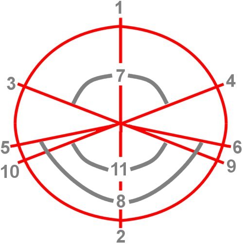
Conversely, the later closing allows unburned gases to escape into the exhaust tract because it is still open and the overflow channels are already closed. There's no question that we would like to reverse this, but this
cannot be achieved with pure slot control via the piston. Regarding the diagram above: The part scavenging is obtained by moving the entire section 7 downwards. Point 9 would then mark the start of the scavenging
process (11), and point 10 the end.
Now the system becomes asymmetrical, due to the effect of the diaphragm valve mentioned in the previous chapter. This does not develop so much at low speeds, so it is not very suitable for the broad power spectrum
expected from the engine, but only becomes effective at high speeds. The intake valve opens significantly earlier before top dead center (TDC) than it closes after top dead center. Even the gas exit is affected by this
asymmetry, although nothing has changed in the exhaust channel.
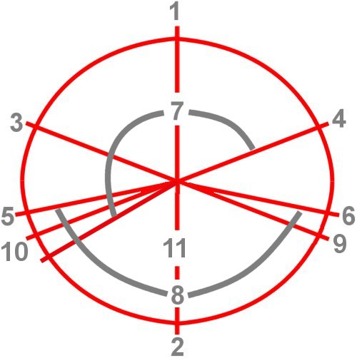
The higher residual pressure of the combustion gases has already been mentioned. However, one would ideally like to maintain this pressure on the piston for a longer period, rather than opening the exhaust port too
early for it. This problem can be alleviated by inserting a flap that partially closes the exhaust channel, which is controlled by a servo motor, for example, depending on the engine speed. Rotary valves in the intake manifold,
as an alternative to diaphragm valves, were once considered promising, but they lacked sufficient durability. All these methods are suitable for making the control of the channels by the piston more flexible.
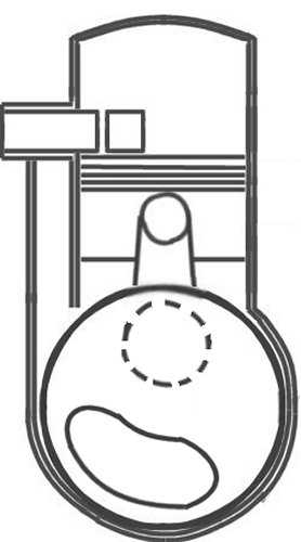
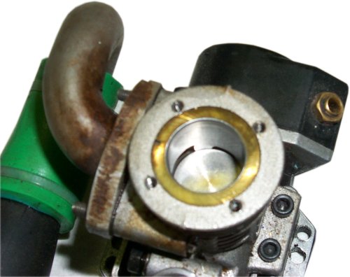
This would be a very simple slider control through an opening in the counterweight of the crankshaft. The intake channel is marked by the dashed line. It opens into the crankcase in such a way that it can be opened and
closed by one of the crank webs. However, the crank webs are not shaped this way for no reason. They are designed to fill the dead space in the crankcase as much as possible, in order to achieve the highest possible
pre-compression ratio.
| Our book on lubrication also deals with the two-stroke engine. |
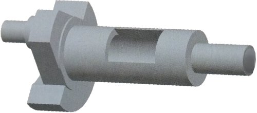
Also worth mentioning are the internal combustion engines used in model vehicles, which are mostly modified two-stroke engines. They work according to the glow ignition principle already used by Gottlieb Daimler and
Wilhelm Maybach. So, a continuously ignited fuel mixture that is constantly supplied with fresh fuel, ensuring that the pressure rises appropriately according to the piston position. This requires precise valve timing, as
illustrated in the diagram below, which shows a hollow crankshaft that also functions as an intake slider. This requires precise timing of the valve events, as illustrated in the diagram below, which shows a hollow
crankshaft that also functions as an intake valve. Honda implemented this principle in the 1990s with its EXP-2 project, using a single-cylinder, 400 cm3 two-stroke engine, participating in the Dakar Rally, and
demonstrating its reliability.
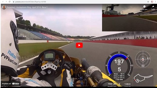
Finally, some (older) cart technology to demonstrate the performance of smaller two-stroke engines:
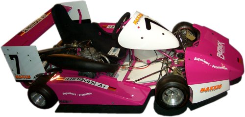
Rotax 256, Single cylinder, 250 cm3, 43 kW (58 PS), 6-speed, mixture 1 : 25, 12 l/100km, 125 kg, up to 220 km/h, 1993
kfz-tech.de/YVe2
|
|