Air-fuel Metering
Actually, we want to get to the measurement of the intake manifold pressure, which would be another sensor after the air mass meter to detect the air drawn in. But whether we get that far, we will
see. Why? Because it would be interesting to find out how the intake air was determined in earlier times.
The simplest answer would be: not at all. That can't be, because if there is too much petrol, the engine will run out or at least consume too much and if there is too little it does not start at all or hardly takes up any gas. And yet
the answer is correct, because they have left it to the air itself to suck in the appropriate amount of fuel.
Sounds easier than it was in reality, but it is not our topic. We are talking about the carburettor, invented by Maybach and constantly improved, in which the intake air was chased through a constriction which, together with the
end of the line opening there, was designed in such a way that the right amount of fuel was sucked in as precisely as possible for each air volume.
But we are looking for sensor technology. Perhaps we will find it in fuel injection, as we do today. But it is not so easy to follow the path along the Diesel engine into the past. shimmy. Some pumps for petrol injection have
been developed from that for Diesel engines, wherei it does not need such a measurement in principle. If there was too much fuel, the engine simply gave off more power. The volume of injection as a measure of the
required power.
And this is how you get to Johannes Spiel's stationary petrol engine from 1884, which is considered the first German engine with petrol injection. An amazing mixture of Ottos open flame ignition and two, partly connected
pumps, a larger one for air and a smaller one for fuel. So the required mixture was pumped into the engine, whereby light changes of 14.7 : 1 were possible depending on the engine speed.
However, all following engines must first be considered as free sucking, even if they are turbocharged. This means that you have no control over the amount of air sucked in. Also the throttle valve is not very reliable. Just take
a look at the overrun mode with partly revving motor and closed flap. An angle encoder of the throttle valve alone is not a reliable sensor for the air volume sucked in.
This is where the so-called barometer cans come into play. If you fill them with normal pressure and place them in an environment connected to the intake manifold pressure, they expand according to this. And it was
precisely this movement that was used to mechanically influence the mixing ratio. You can also reverse the suction tube pressure in the barometer cans into a conducting enclosure with external pressure.
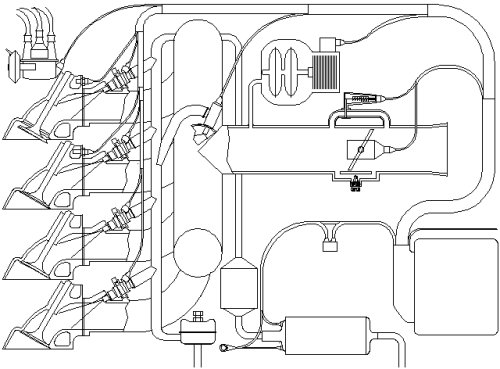
In the case of aircraft engines, there were even up to three cans, each one additionally responding to the flight altitude and the pressure from the turbocharger. This design was also retained when the first electronic fuel
injection system was conceived. The pressure sensor (Drucksensor) even gave the D-Jetronic its name. At the top, it is located in the middle of the corresponding system.
The barometer cans function in the same way as in purely mechanical times, only here they are connected to the moving iron core in a magnetic field. Depending on the pressure in the chamber, they influence this field and
thus provide the control unit with information about the conditions in the suction pipe.
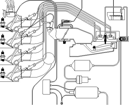
The next generation of load sensors appears somewhat less elegant. You will find them both in the subsequent L-Jetronic and in the again purely mechanical K-Jetronic (kontinuierlich) above. Actually not so nice, an
additional flap in the intake manifold, but obviously it had advantages over the barometer cans. The air volume meter in the L-Jetronic even needed additional compensation against vibrations.
The latter is densely packed in its evaluation chamber with lasered resistance tracks that are mechanically scanned. Probably the resolution was not sufficient for an angle of almost 90¯, so that the resistance value always
decreases after setbacks. The reliable contact in each flap position is checked in the oscilloscope by traversing the entire measuring path as a so-called noise test. Interruptions are immediately noticed.
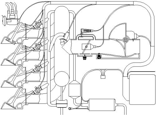
Finally, a special feature in the history of injection systems. Unless the videos haven't been taken back, here the mechanical Kugelfischer injection with space cams. A two-dimensional map is grounded into a truncated
cone-shaped space cam. Influenced in the axial direction by the throttle valve position and in the direction of rotation by the engine speed, it can determine the start of the delivery stroke and thus influence the delivery rate.
However, with any modification to the motor the cam must be at least partially re-determined.
You see, there was too much for the MAP sensor after all. See you next time.
|