 Hydraulic power steering Hydraulic power steering
Correctly it should be named 'power assisted steering'
Already with the shift of the drive to the front or if for other reasons more weight is on the front axle, respectively the tires are wider, sometime the steering is too sluggish and may have to be designed very
indirectly, to be still reasonably manageable. This is what the American producers already understood, as they wanted to attract more women as drivers in the 50s of the last century.
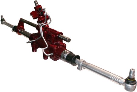
Rack and pinion power steering in trucks
You can easily test how strong supports your steering. Let roll out your vehicle only on a large empty place or a corresponding road with the ignition off. But please, remove the ignition key in no case. What do
you now feel at steering forces, is the net value. For some people it's enough already, to want to move the steering at a standstill with ignition switched on.
Just as it does not work in front disc brakes without brake booster, power steering is essential even in modern vehicles above the small car class. And the was hydraulically a long time, first, of course,
introduced in the luxury class. Sometimes it has even been carried out as 'central hydraulic' and replaced in addition the pneumatic brake booster by a hydraulic.
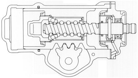
We have talked about the recirculating ball steering. The really needs not much in order to be hydraulically supportable. Supposing, a central hydraulic pressure of 140 bar, separately only for the power
steering of 100 bar, then this pressure is at one of the two lines at top while driving. The respectively other is connected to the return flow in the supply container.
Can you see how the ball nut is moved respectively back and forth, and thus the steering operation is supported? This requires a corresponding seal, which is drawn in as a type of oil-seal ring in the outer
housing slightly to the left. The decisive factor is of course the control, but more on that later. Now is to see here yet the corresponding sectional image.
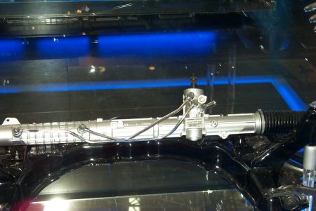
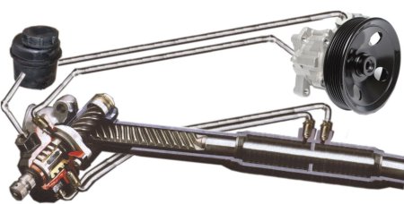
Then below, slightly compressed a complete system for a simple rack and pinion steering. Left the supply container again, right the pump which must be driven from the engine, of course, by V-belts or in this
case, ribbed belts. Underneath then, the steering gear with an additional workspace in the center. The allows it to exert pressure on the toothed rack in the respective direction.
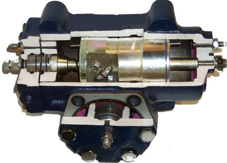
The most important component in this picture, probably the most difficult to understand is the control of the hydraulic flows at the bottom left. To be able to explain the very important processes in the control
unit for understanding of a power steering, we have a (together tinkered) model here.
Look first to the parts already known. There the steering wheel, which moves back and forth the steering column via the steering column and the pinion. To the right the workspace, which fills the right working
chamber with pressure oil when steering to the right and the left working chamber when steering to the left. Very important is the simultaneous pressure reduction on the opposite side.
Should you be amazed when looking to the steering column, then you are right. Because it has not everywhere the same cross section. The narrowing is highly wanted. Through this should be incorporated a
defined elasticity. I.e. the part up to the steering gear is supposed to operate together slightly offset with the upper. Exactly the angle and the torque, this is necessary to move the lower part also, form the
trigger for the intensification by oil pressure.
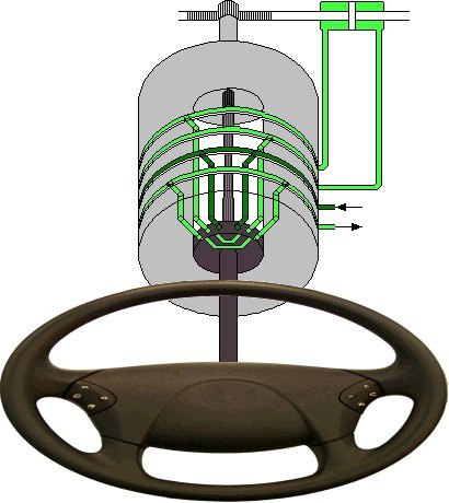
Now the light gray drum with the many holes and ring grooves comes into play. From top to bottom it is connected to the return flow, the pressure side and the right or left working cylinder. The drum is
connected to the lower part of the steering column, beyond the part with smaller cross section. However, the darker distributor is on the upper part of the steering column.
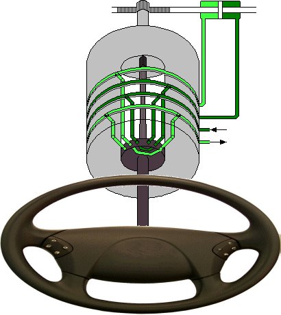
So now we have turned the steering wheel slightly to the right. The force or the torque was strong enough to twist the thinner cross section in the steering column. The lower part and the gray drum too are still
not followed the small rotary movement on the steering wheel. This results in the possibility for the distributor to connect the first ring groove with the fourth and the second with the third.
From now on the steering movement is supported, toothed rack and lower part of the steering column moved. Therewith then the gray drum is combined, too, by its rotary movement be interrupted the
connections created by the distributor. The whole spook of support of a steering movement is over. A similar process is initiated when turning the steering wheel to the left.
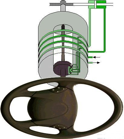
Here is deflected a little further to the right. The gray drum almost completely took part in the rotation, is still connected via the four ring grooves hydraulically with the housing. The torsion bar below in the
steering column is still under torsional stress, so that the distributor connected to the steering wheel ensures pressure in the right chamber of the working cylinder in the toothed rack.
The steering support basically ends only then, when the torsion bar is no longer twisted, means the toothed rack has fully adjusted to the steering wheel position.
We have singled out exemplary a controller, in order to explain the principle. We note every little steering movement triggers an incident and the resulting pressure loss in the course of this must be refilled by
the continuously running pump. The controller has its place mostly at the entrance of the steering column to the steering gear, irrelevant whether toothed rack or recirculating ball steering.
So the only thing missing is the supply with pressure. Correctly, it is necessary to distinguish two situations when the pump is running. If sufficient pressure is present, then so to speak it's a kind of idling.
Only when this drops too much, the pump must continue to fill up the system, however, counteracting against the high residual pressure. A pressure accumulator, a nitrogen chamber with 90 bar separated by
membrane, can help to reduce energy-saving the number of filling phases.
By the way, the brakes as the first get to feel the pressure for safety reasons. In the central hydraulics are possible maximum 150 bar by a safety valve.
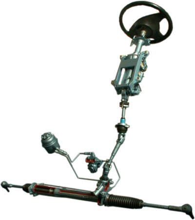
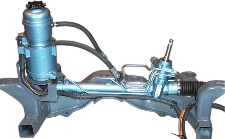
Here once more all parts at a glance. The oil tank left with filter insert, right next to it the high-pressure generator, arranged close to the engine, e.g. as a vane pump. Then below the toothed rack with the two
working chambers. Just above the hydraulic control, here by a so-called rotary piston valve. The individual components were connected by steel pipes respectively high pressure expansion hose.
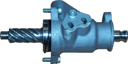
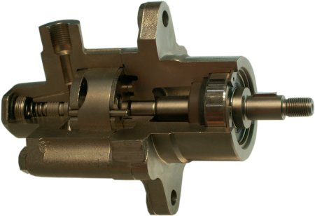
The controller has already been explained and can be seen here as a compact part, together with two of the connections. Below follows a picture of the pump, the driven by V-belts or ribbed belts sucks the
hydraulic oil from the container and delivers under high pressure to the rotary piston valve to the steering column.
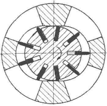
The vanes in the rotor are pressed by the centrifugal forces during the rotation against the cam ring of the housing wall and seal thereby. There where the volume between them decreases, is the pressure side,
the suction side where it becomes greater. In the picture below would be at clockwise rotation above the pressure side and below the suction side.
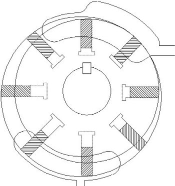
Similarly, the double acting vane pump operates. It can remain with one rotor and the same number of blades. But, the cam ring is shaped differently now. It now has two inclines of half a revolution each. Two
pouchs each are required for the suction and the pressure side, even if they are combined into one line shortly before or after. In any case, twice the delivery rate per revolution is achieved.
In the pressure pipe we find the pressure limitation already mentioned, a spring-loaded valve that opens when exceeding against the flow line. Similarly, the so-called flow limiting valve works, only with a weaker
spring (e.g. for 75 bar) and a significantly larger cross-section. Together with a throttle in the pressure pipe can be reached with the flow limiting valve a pressure reduction at increasing engine rotational speed.
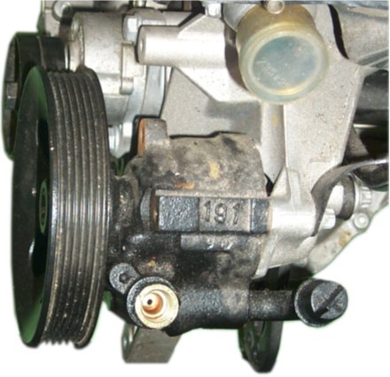
Here a modern power steering pump.
That would mean at higher speeds on the highway, where is driven generally in the same gear, less steering assistance. The associated greater feeling in the steering is explicitly welcome. Of course, a real
speed-dependent regulation of the assistants this is still not.
So, by the way, looked one of the first power steering systems.
|