|
| 
|
 Auxiliary heater Auxiliary heater

The auxiliary heater does not have the problem of severely limited heating capacity, regardless of whether it is an air-based or coolant-based heater. Since it runs on fuel supplied from an external source, there is enough
energy available. There is a suitable auxiliary heater available for every type of fuel when retrofitting.
| Reasons for shutdown |
| Desired temperature reached |
| Coolant outlet temperature too high |
| Excessive difference between input and output |
| Fuel shortage |
| Overvoltage/Undervoltage |
| Vehicle electrical system overloaded |
| Airbag activated |
In addition to the high installation costs, such a system has another, much smaller drawback: it must not be operated in enclosed spaces. But let's not start talking about a possible garage heater just yet; after all, it's
warmer in there than outside even without one. And you don't have to scrape the windows there either.
When retrofitting, the cabin heating circuit is opened at precisely designated points, and the heater is clamped in between.
Of course, converting the chemical energy stored in the fuel directly into heat, without going through the electrical system, also offers significant advantages in terms of efficiency. There are even electric cars that have
retained a small fuel tank for this purpose, thereby extending their range. If you forget to fill up, you'll 'only' be punished with a cold interior and possibly windows that keep fogging up.
| It's important to heat up quickly. |
If it heats the coolant independently of the engine, it is sometimes also referred to as an auxiliary water heater. For example, in luxury models, they are also available as an optional feature from the manufacturer, who, of
course, emphasizes just how much a cold interior compromises road safety. In many regions, the temperature is subsequently expected to remain below 5°C for one-third of the year.
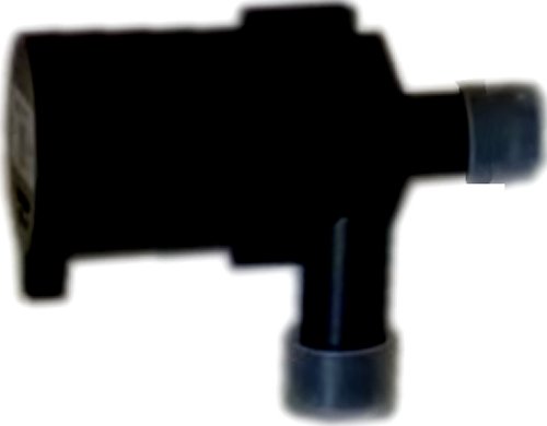
The picture shows the water heater itself. In the center is the combustion chamber, the central element. Surrounding them, filling the entire intermediate space, are the exhaust gases, which are designed to transfer as
much of their heat as possible to the coolant in the surrounding space. They then get out at the bottom and make their way to the silencer.
| Integration with the rest of the engine and vehicle components is particularly important in hot-water
heating systems. |
Some parts of this facility are monitored. Only one of the two coolant connections is visible; the other is hidden. But here too, there is an active check between entry and exit. If, for example, a sufficient flow rate is not
maintained, e.g., due to insufficient pump capacity (see figure below), and the temperature difference exceeds 15°C, the system will shut down just as it would if the outlet temperature exceeded 85°C.
Equally important is the monitoring provided by the flame sensor, which, unlike the two temperature sensors at the water inlet and outlet, is a PTC. Both NTCs follow a certain
long-standing standard for many NTCs, namely approximately 20 kOhm at 25°C, naturally decreasing at higher temperatures. The opposite is true for the PTC. And since it gets hotter in the combustion chamber, here it is
about 1 Ohm at 25°C, and it naturally tends to increase.
| Additional components |
| Control unit (on the water heater) |
| Pump and valve assembly |
| Shut-off valve for coolant |
| Fuel metering pump |
| Radio receiver, antenna |
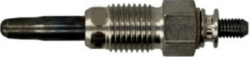
Problems with the glow plug (pictured above) are generally more difficult to diagnose. In this case, it would be 0.5 ohms, though these values should not be interpreted too strictly. Since the glow plug also has PTC
properties, its resistance increases as the temperature rises, which effectively acts as a form of self-limiting mechanism. However, the winding becomes very hot, which can still cause a malfunction in this condition, even
though the resistance value was normal at room temperature.
| If there is enough space, you can also install or remove the heater while it is still mounted, but you
must first relieve the pressure from the cooling system. |
Newer devices should be capable of self-diagnosis. At first, it was actually a flashing code that was transmitted via the two wires to the glow plug. Apparently, you could even hear it. At least that made it possible to display a
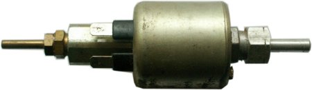
simple error message. But we've already made some progress. The electric motor (far left in the top of the picture) is still missing; its fan provides the much-needed combustion air. It must be able to rotate freely
and should run when connected to a power source, even if the control unit is otherwise disconnected.
And one more thing: A diesel-powered auxiliary heater, for example, has similar issues on short trips as a diesel engine. It doesn't reach operating temperature and cokes. Inside, the glow plug is designed to operate only
until the fuel-air mixture ignites reliably on the hot sieve surrounding it, which can be difficult if there is too much soot buildup. Sometimes, all it takes is taking it apart and cleaning it.
And one more thing: Even modern internal combustion engines have this annoying tendency where, even after the actual problem has long been fixed, the warning light doesn't turn off on its own.
This can also happen with a fuel-powered auxiliary heater, because special rules apply in this case. You'll need to access the error log and delete the entries there.
| Typical specifications of an older coolant heater |
| Heating capacity | 4.300 W |
| Coolant flow rate | Aprox. 900 l/h |
| Power consumption | 48 W |
The components are also distributed throughout the vehicle for packaging reasons. The system is started by turning on the combustion air blower and the fuel metering pump. Once you connect them to the power source,
nothing happens except for a single internal jerk. Here, a pulsating current drives a magnetic keeper, which moves a piston back and forth in time with the current, making it easy to dose.
Perhaps the buildup of soot will cause less of a problem if the filter is removed. Such systems operate on the Venturi principle, as we know it from carburetors. In this process, air is drawn into the fuel
by means of negative pressure. However, the fuel-air mixture burns right into the flame tube as well. The heat generated is transferred to the coolant in the water jacket, while the combusted gases are routed through a
separate exhaust system equipped with a muffler and precisely defined length.
|
|