Car-Technology: Engine Control 3
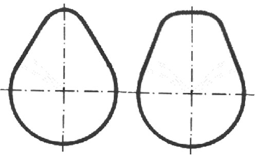
Two cams side by side with the same stroke, yet so different. Based on what you've learned in the previous chapters, you should actually be able to answer the question of which of the two is the one with higher
performance for an internal combustion engine.
At first glance, you might tap the one on the left because anything that's more pointed seems to indicate higher performance, but of course it's the one on the right, because its valve opens and closes faster. So
on average, there is a larger opening cross-section, which means more filling.
So if you were to change the right one for the left one, you couldn't really go wrong, since 'Entrance opens' and 'Entrance closes' are obviously located at the same spot. The stroke is also the same, which means the valve
cannot collide with the piston.
And yet this assumption may be incorrect, because the fill levels are calibrated in such a way that they may remain constant over a relatively wide range of engine speeds for the left cam. On the right cam, they are
undoubtedly larger, but this can also cause them to flow back into the intake tract, leading to undesirable effects.
It just means that you shouldn't always look at just one aspect of a phenomenon; instead, you have to examine it holistically. The opposite is true when you look at how a cam like this rolls off a
cup-type tappet. Below is a picture of one without hydraulic valve clearance compensation.
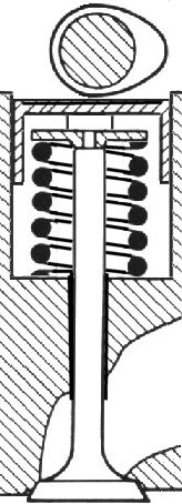
Perhaps it's becoming a little clearer now why the diameter of the cup-type tappets has to be so large. When the cam is rotated clockwise, the line of contact - which runs perpendicular to the cam - initially begins roughly in
the middle. It then moves relatively far to the right, eventually crossing the center to the far left before returning to the center.
It should be clear at this point that this creates a considerable moment of overturning, so the tappet should be designed to be relatively high. Below is the design featuring a hydraulic tappet. In terms of the overturning
moment, there is hardly any difference here. After all, in these two designs, the valve's path is exactly the same as that measured at the cam.
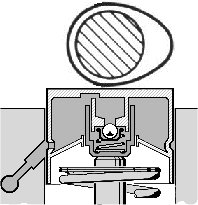
By the way, it's not entirely clear which one runs out of steam at high speeds, the inlet to the working chamber or the outlet. That is another reason why hydraulic tappets are rarely used in racing engines or heavily tuned
engines. In most cases, the drain fails when the engine is running at high RPM for an extended period, causing the working chamber to expand continuously until, eventually, the valve remains slightly open, with the well-
known potential consequences.
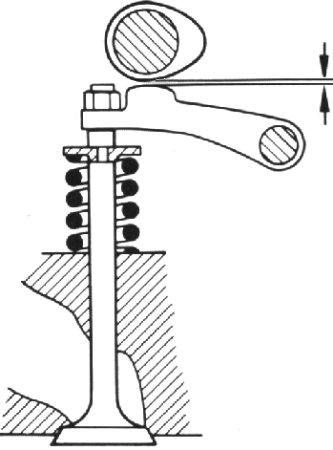
Here is a design in which the effect of the gear ratio at the follower lever is added to the contour of the cam. Can you perhaps imagine that the path of the contact line during the opening of the valve might also play a role
here? The curve on the cam follower toward the cam acts like an even sharper curve on the cam from the base circle to the tip.
And so it may indeed be that the cam at this point is not convex, as is customary and shown throughout this article, but rather concave, in order to compensate for the resulting excessive curvature. So don't
be surprised, because the valve will open as usual. In general, one cannot assume that the rising and falling cams must always be the same.
Why did we actually emphasize earlier how large the cup plunger needs to be? Because, of course, the weight of the entire valve actuator plays a role; the spring must overcome its mass inertia
before the piston potentially strikes the valve. By the way, it itself counts as about half, but the rest as a whole.
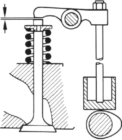
Here's an example of a valve train with a pushrod and a lower camshaft. This motor certainly can't handle 10,000 rpm; the spring simply can't be strong enough for that. But you are given an acoustic warning, especially
here, because you can hear the valves fluttering when the valve spring can no longer keep up with the backward movement.
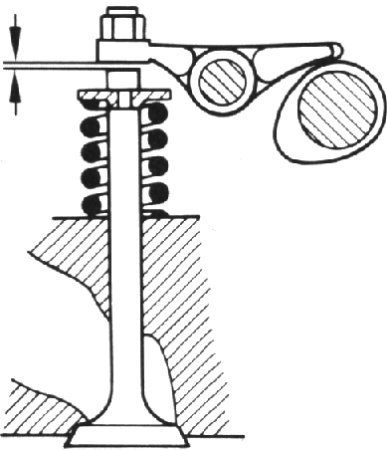
Rocker arms can also be used with overhead camshafts, although in such cases they are usually positioned slightly to the side of the valves rather than above them. Unlike the previous image, the adjustment option is
shown more accurately here, namely with a lock nut on the valve side. A gear ratio is also possible here.
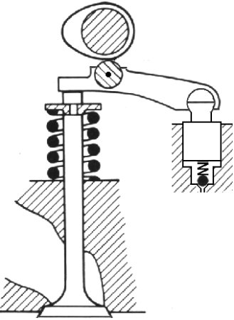
Finally, all the advantages are summarized once again in a single design. There is no longer any need to adjust valve clearance, and there is no longer any sliding friction caused by a roller between the cam and
the rocker arm, a feature that, incidentally, has since become standard in the other two designs as well. And as a highlight, the hydraulic tappet is positioned in such a way that it is no longer part of the moving masses.
|