Clutch 1 Clutch 1

| 1 | Flywheel |
| 2 | Clutch disc |
| 3 | Pressure Ring |
| 4 | Diaphragm spring |
| 5 | Clutch Cover |
| 6 | Transmission Input Shaft |
| 7 | Crankshaft |
A standard manual transmission won't work without a standard friction clutch, in this case, a dry one. Just as the transmission must respond to the limited speed and, above all, torque range
of the internal combustion engine, the clutch must respond to the need to change gear ratios, silently and with minimal wear.
So if the engine and transmission are not separated from one another in certain situations, the expectation described above simply cannot be met. We'll stick with this type of clutch in combination with the
manual transmission. We consider starting off and shifting gears to be situations in which the clutch is needed, regardless of whether we're shifting up or down. For the clutch, the challenge is usually the
starting off anyway.
Throughout history, there have been several attempts to automate the clutch. If it was divided into a shift clutch and a start-up clutch on that occasion, the latter was often twice as large. To be more precise:
The clutch tends to wear out especially when you're engaging it. And if the transmission input shaft is at a standstill at the start of the engagement, the most. So, the situation right as you start driving.
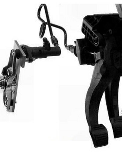
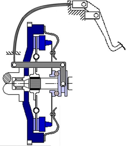
The clutch described here is operated by a pedal that is located on the left side of the pedal assembly, even in right-hand-drive vehicles. Power is transmitted from the pedal to the clutch and transmission less
often via a linkage, much more often via a bowden cable, and, starting with mid-range models, now almost exclusively via a hydraulic system (see image below). In this case, the operating forces are quite
the lowest.
So, what actually happens when you press the clutch pedal? Sure, it separates the engine from the transmission. But how does it disaggregate the two? To do that, we'd first have to figure out exactly how the
two are connected via the clutch. We are dealing here with a force-locking connection, not a form-locking one of the type found in the subsequent manual transmission.
It can - and usually does - slip a little when accelerating. If this happens for a somewhat longer period of time, we call it: letting the clutch 'slip'. This happens to people who don't want to or can't decide whether
or not to disconnect the engine from the transmission. The result is often the same as significantly easing off the gas pedal. But people like that often don't want to do that, because they're afraid they might
stall the engine.
This sometimes stark contrast between the engine running and the vehicle not moving forward results in unnecessary noise and fuel consumption, but that's not the worst of it. If you disassemble clutches that
have been treated in this way, you'll find that the inside is black with tiny particles of the clutch lining that have been worn away in a hot fluid. There's a lot to clean, and not just wear parts, but also everything
exposed to heat needs to be replaced.
It serves you right. Why don't you start off properly, by releasing the clutch just fast enough so it doesn't jerk? Is that too much to ask? Of course, you have to practice this a bit, often with every new car or maybe
even after a clutch repair. If you take good care of it, it'll last forever, even with frequent use.
In the past, however, a clutch that was hard to engage at higher engine speeds was sometimes a problem for women. No, not for luxury sedans, they had automatic transmissions anyway. The problem
tended to arise more often with sports cars, specifically, those that truly deserved the name. In such situations, the clutches were also not fully depressed, much to the chagrin of the transmissions.
| A transmission can suffer in silence - even a modern one. |
As you've probably noticed, friction plays a major role in the clutch. And if there are no assistants, the pedal force required to disengage the connection depends roughly on the engine power. The mechanical
gear ratio between the clutch pedal and the actual lever on the clutch simply cannot be increased arbitrarily, because there is only a certain amount of pedal travel available.
Basically, you have to imagine two shafts, each with a disc at one end, one made of polished steel and one with a friction lining. They are compressed by one or more springs. In a motor vehicle, however,
two disc-like components are connected to the crankshaft. Accordingly, the disc positioned between them and connected to the transmission has friction linings on both sides (Figure below).
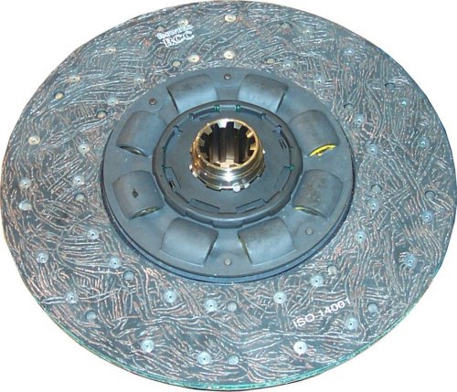
| Given the coarse teeth, it's more likely a clutch disc from a truck. |
To put it simply: Enough torque must be transmitted so that a secure connection is clearly guaranteed only when the disc on the transmission shaft is clamped between the both on the crankshaft. Incidentally,
the former is called the clutch disc or drive disc, while the latter two are the flywheel and the pressure plate. To disconnect the coupling, the pressure ring must be moved slightly away from the flywheel to
release the clutch disc.
As you might have guessed, this requires that the clutch disc is connected in a rotationally fixed manner to the transmission shaft, but still be able to move freely axially; otherwise, it would still be connected
to the flywheel, which in turn is bad for the transmission. Please be sure to check this before installing a clutch disc. This is because it is installed on the engine side, but the inspection can only be performed
on the transmission, which, in the vast majority of cases, has been removed to gain access to the clutch.
The question remains as to how the movement of the clutch pedal functions as a lifting mechanism for the pressure ring. It should be noted that this is, as is normally the case with any detachable coupling, a
rotating part. For this reason, an axial bearing—also known as a release bearing—is installed on the transmission shaft; the transmission side of this bearing remains stationary and is connected to the clutch
pedal via a release lever, while the engine side rotates at the same speed as the pressure plate, either continuously or only when necessary.
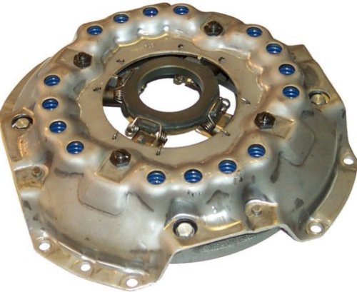
kfz-tech.de/PGt19
Früher und bei bestimmten Spezialkupplungen (Bild oben) z.B. für landwirtschaftliche Geräte war das einfacher zu verstehen. Da gibt es einen mit dem Schwungrad verschraubten Deckel mit im obigen Fall 16
Ausbeulungen, in denen sich Schraubenfedern befinden. Die drücken dann auf den Druckring und pressen damit die Kupplungsscheibe ein. Zusätzlich sind da wiederum 4 Hebel auf dem Umfang verteilt, die
durch die Bewegung des Ausrücklagers den Druckring zurückholen können.
The disadvantage of coil springs is that the force required to operate the clutch increases the harder you press the clutch pedal. But it should actually be greatest at the point of pressure. This is the range of
pedal travel at which, when you release the clutch, the car just begins to move. Furthermore, applying increasing pedal force is unnecessary and only encourages the incorrect technique described above.
That is why, for quite some time now, a diaphragm or disc spring has been used to press the pressure ring into place. It is designed in such a way that, for the rest of the distance beyond the pressure point,
it curves outward toward the other side and, in principle, actually requires less force. In addition, it eliminates the need for small transmission levers.
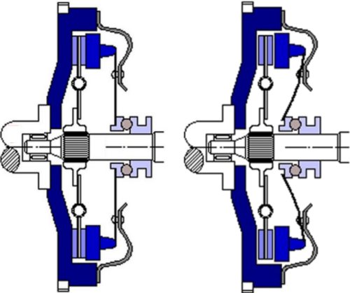
Here is a diaphragm spring clutch in its disengaged state on the left and, slightly exaggerated, in its engaged state on the right. The diaphragm spring thus serves the dual purpose of clamping
the clutch disc between the flywheel and the pressure plate and acting as a transmission medium for the release. Below is another illustration showing how the clutch is connected to the pedal. As mentioned earlier, the
cable pull is more commonly found in the A or B segments.
|