|
| 
|
 Basics 3 Basics 3

Basically, it continues in the same way as in the previous chapter. We just need to be a little more modern, because the front-engine, rear-wheel-drive layout has long since ceased to be the norm. Front-wheel drive clearly
dominates. And this is where things get a little more complicated, because we’re no longer dealing strictly with a longitudinally mounted engine; instead, it can now be mounted transversely to save even more space.
You'll be amazed at what's possible with an engine like this. Engine side, a V8 has even found its place here, although it was specially designed for this purpose and not exactly in the narrowest vehicle.
Except for the large engines, everything seems to be possible here, just as we've come to expect. Who would have thought that there would one day be Jeeps with a transverse engine and all-wheel drive?
And what are the consequences of having the engine and transmission together at the front? The flow of energy, as indicated by the symbol in the upper left corner, can no longer occur. Then the
order would be: engine, transmission, axle drive. No, in a front-engine with front-wheel-drive and, incidentally, in an engine, next to the rear axle with rear-wheel-drive as well, the axle drive is positioned closer to the engine
than the transmission.

Here you can see both arrangements again. The left-hand configuration is now the most common, with a transverse engine, while the longitudinal engine configuration is really only used when the series includes very
large or wide engines. In practice, the configuration shown on the left is used exclusively with engines having up to four cylinders, with occasional five-cylinder inline engines or VR-5 and VR-6 engines. What seems to be
important here is the space that may have been factored in for a hybrid powertrain.
The right-hand drive configuration, of course, has the obvious disadvantage of making the vehicle top-heavy. Instead, it has all-wheel drive, which is somewhat easier to realize. However, the pair of toothed wheels
does not appear to be necessary in a transverse engine to achieve this aim. In the history of the automobile, both types of drivetrains have, of course, been used at the rear as well, even with the engines positioned in front
of the rear axle.
In general, both drive systems strain the drive axle, which can be useful in winter. They are also likely to be slightly lighter because they lack a cardan shaft and its bearings. In addition, the axle drive is usually no longer
recognizable as such, because it is integrated into a common housing with the transmission. However, we are focusing exclusively on the transmission division here.
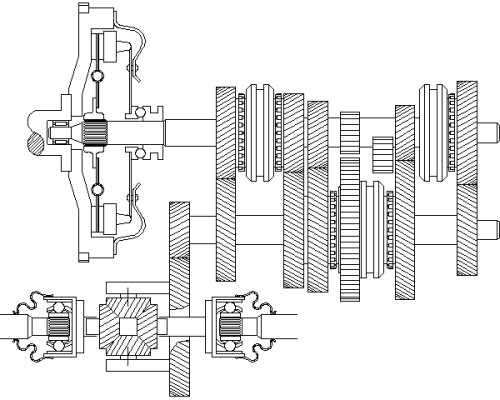
Here you can see the inner workings of the drivetrain beyond the internal combustion engine. Only his left coupling is shown in the drawing, so that one can infer its orientation. And now here’s the surprise: If you look very
closely, you'll notice that the transmission part is the same in the illustrations above and below. For now, we will ignore the last tooth wheel on the output shaft, since it is part of the axle drive.

And the transmission doesn't care at all whether its drive shaft passes through the housing section of the axle drive, as is the case with the longitudinal arrangement of the engine and transmission. The main thing is that
the output shaft comes out on the same side where the input shaft went in.
Of course, we deliberately arranged the gears in both transmissions in as similar manner as possible. It’s a somewhat strange arrangement, that can only be explained by the development of the manual transmission.
It basically started with three gears, was then expanded to four gears, and, as is now clearly evident, to five gears. So each of the two transmissions actually has four gears, which were later expanded to five. Try narrowing it
down yourself.
Therefore, we will initially disregard the upper right shift sleeve and the subsequent pair of gears. Then it should be clear that, starting from the drive shaft connected to the clutch, the gears are arranged from left to right as
fourth, third, second, reverse, and first. Unlike the transmission described in the previous chapter, the drive shaft is not split. We therefore also refer to this transmission as "two-shaft" in contrast to the "three-shaft" type
already explained.
So there is no countershaft, only an input and output shaft. Now you could reattach all the wheels to the output shaft instead of the countershaft. But that’s not usually what is done; instead, they are distributed across both
shafts, as shown here. So, for fourth gear, the upper left shift sleeve must be moved to the left, and for third gear, to the right. To shift into second gear, move the lower right shift sleeve to the left; to shift into first gear, move
it to the right.
For reverse gear, which is also unsynchronized in this case, the straight-toothed intermediate gear must be pushed into the slot between the two remaining straight-toothed gears, naturally with the lower right shift sleeve
in the middle position. Now we can finally add the fifth gear by moving the shift lever to the right. In transmissions retrofitted in this way, the fifth gear may also be located outside the transmission housing, protected only by
a cover.
Another important difference from the transmission discussed in the previous chapter. Because the input and output shaft are aligned here, it is also referred to as 'coaxial', whereas this is not the case with our two
transmissions, which are therefore 'non-coaxial#. The difference between the two gearboxes discussed in this chapter is that the output shaft has a spur gear in the transverse configuration and a bevel gear in the
longitudinal configuration.
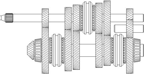
Here is another non-coaxial gearbox in a longitudinal configuration. Hopefully you can tell just by looking at it, it was designed with five gears right from the start. They're all lined up nicely one after the other. Another change
can be seen in the helical gear wheels of the reverse gear. It is now also engaged via a synchronizer ring. Since there is usually a synchronizer mechanism underneath, you can still shift into gear even while the vehicle is
still rolling.
kfz-tech.de/PGt20
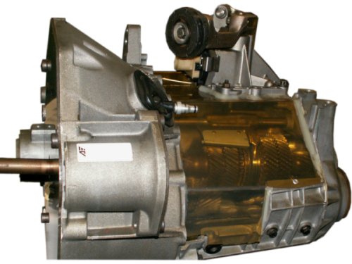
So this is what a two-shaft, transversely mounted five-speed transmission looks like. Your task is to determine the transmission wiring diagram based on this information. To present the solution in a way that’s not only
simple but also easy to grasp, here’s a one-sentence description. The fifth gear is on the front right, and the reverse gear is directly across from it.
|
|