 Basics 1 Basics 1
You can twist and turn it any way you like, but somehow someone who has bought this book expects the subject matter to be made accessible to them from the ground up. And that is exactly what we will do in
this chapter and the next. So if you already have a good understanding of simple manual transmissions, then I'm afraid you'll have to skip ahead.
However, you may also wish to stay if you are curious to see whether there is an aspect here that you have not yet given enough consideration to, as we intend to cover the topic of four-speed manual transmissions in
some detail. So, enough of the introductions, let's just get started.
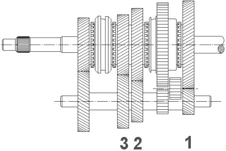
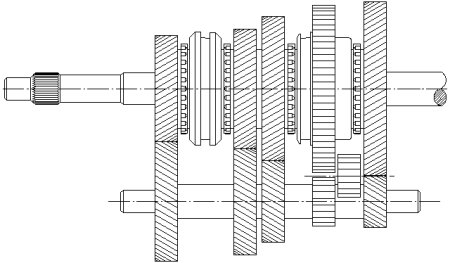
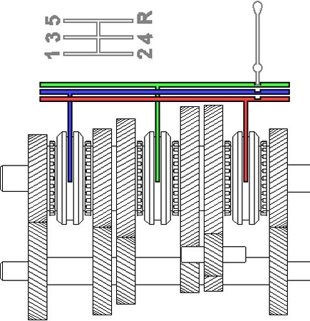
So there are four gears, the first three of which are relatively easy to identify from right to left. You have to skip the one in between, because that is reverse gear, recognizable here by its straight teeth and the retractable
intermediate gear. In the simplest four-speed transmission, reverse gear is always located quite close to first gear because it has a similar gear ratio.
| Gears that are permanently connected to their shaft are marked with an 'x'. |
No, the gear pair on the far left does not represent fourth gear. It would be a big mistake to assume that with this transmission. Why? Because we are assuming a so-called 'standard drive' here, even though this is no
longer standard nowadays. So, in this transmission, the engine is positioned longitudinally at the front, and it continues to the right via the cardan shaft to the rear axle.
In order to be able to insert a gear ratio, we must therefore leave the input shaft and return to the main shaft at some point in the first three gears. There are then always two gear drives with a total of four gears in between.
This means that the output shaft on the right generally has a different speed than the input shaft on the left in the first three gears.
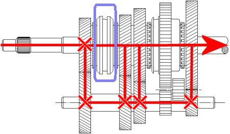
As you have probably already noticed, the upper shaft consists of two partial shafts that are inserted into each other but can be rotated against each other, although they must be aligned with each other. The connection is
hidden under the upper left pinion gear. We still need to clarify the significance of the switch sleeve next to it. We have generously outlined it in the image above.
And how does the fourth gear work? Quite simply, by removing the separation point and connecting the partial waves to each other. That's right, there is no transmission in the gearbox. As you can see in the image above,
this only occurs between crown and bevel gear. The two decide together which gear ratio to use in fourth gear.
Perhaps you have heard of a ‘short’ or ‘long’ axle. This has nothing to do with the actual length of a driven rear axle, but refers to its transmission ratio. 'Short' refers to a high gear ratio with high engine speed at a given
speed, and 'long' refers to a low gear ratio.
The 'long' axle is often referred to as a 'creep gear', which is good for the engine and fuel consumption but not so good for acceleration. As a rule, the car is also slower at full throttle on flat terrain, but that doesn't
necessarily mean that the shorter rear axle ratio makes it faster. It may have a too short ratio, for example, but more on that later. However, please note that a different axle drive can change the overall gear ratio of all gears.
You have probably already noticed that not all wheels can be firmly connected to the respective shaft on which they are located, because then the entire transmission would lock up. On the lower drive shaft, we refer to 'fixed
wheels' and on the upper main shaft to 'free wheels'. Although this is not apparent from the respective drive gear, it can be deduced with certainty from the fact that there is a shift sleeve next to each freewheel.
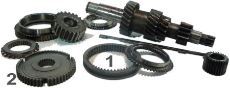
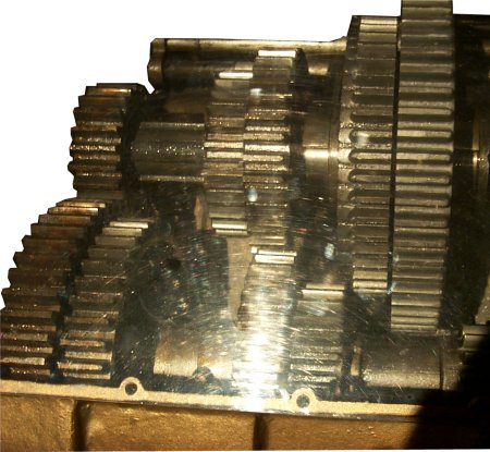
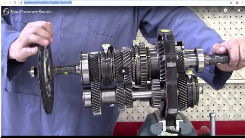
Here we have a small collection of transmission parts, e.g., at the top right with the incomplete countershaft. What is important for us now are the coupling sleeve 1 and the synchronizer 2, the latter of which initially only
connects the shifting sleeve to the shaft. It is therefore firmly connected to this, while the shifting sleeve can be moved on the shaft not in the direction of rotation, but very well in the axial direction.
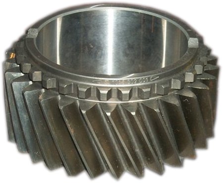
Here is the first real image of a gear wheel with helical teeth. First of all, you can see the smooth inner bore, which indicates a freewheel. That it's not always equipped with floating bearings, we'll talk about that later. Then
please note the helical gearing, which is also still to be discussed. But we are now concerned with this small pre-toothing on the upper edge of this gear wheel.
So, we have moved the shift sleeve to the right. It now connects the former idler wheel to the synchronizer body fixed on the shaft. This then becomes the fixed wheel. The gear is
engaged. If there were only one shift sleeve, e.g., in a two-speed transmission, the only synchronizer ring available could only shift to one gear or the other. With our four-speed transmission,
the situation is quite different.
But where is the second switching sleeve anyway? The left one between fourth and third gear is clearly visible, while the right one between second gear on the left and first gear on the right is badly distorted by the
additional gear wheel for the reverse gear. This is therefore also moved when one of the two gears is to be shifted. But rest assured, inside it looks exactly the same as the left-hand shift sleeve.
And how do you engage the reverse gear? This is what the small intermediate gear is for. To recap briefly: the 1st/2nd gear shift sleeve, like the other one, is always connected to the shaft below in a rotationally fixed
manner. The corresponding wheel on the countershaft anyway. So, by inserting an intermediate gear, a gear with reverse rotation can be engaged, i.e., reverse gear. Incidentally, it does not change the gear ratio between
the two large wheels.
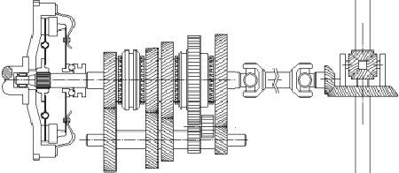
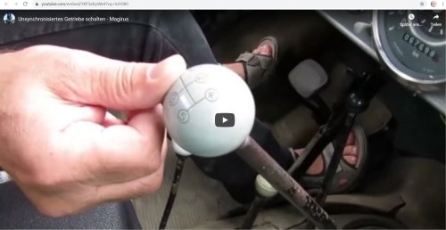
And why is reverse gear straight-toothed? Fresh from the museum, here is an old slide valve gear. It has no shift sleeves, and usually two gear wheels are connected to each other and mounted on the respective shaft so
that they can slide but not rotate. Gears are shifted by meshing gears with each other. The gearbox is significantly more compact in terms of length.
However, there is a disadvantage: straight-toothed gears are more noisy and can transmit less torque. Furthermore, such a transmission cannot be equipped with synchronization. This means that you have to double-
clutch every time you change gear, and when downshifting, you even have to double-clutch with a defined amount of double-throttling. I can still see the driver of an old English double-decker bus in front of me, clutching the
gear stick with both hands and repeatedly changing gears, double-declutching, and changing gears again. The intended gear just wouldn't engage.
In the end, you can only stop and start again. And the gearbox made quite a noise. You can generate exactly that with the gearbox explained here. You just need to roll forward a little while trying to engage reverse gear.
There are already enough vehicles where this is no longer possible because the reverse gear is synchronized, but the older and cheaper the vehicle, the greater the chance. No, trust me and don't do it.
The question of how to prevent two gears from being engaged at the same time has still not been clarified. This is where the famous H-scheme comes into play. You can take it as you like with a car, it is almost always the
basis of shifting, even with a gear lever on the steering wheel and even with the somewhat awkward shift pattern of the Trabant and earlier DKW models. Motorcycle transmissions may be a notable exception.
This time we are using a five-speed transmission. You can see how easy it is to expand the basic transmission to six speeds, for example. The straight-cut reverse gear is also missing here, so shifting gears while the
vehicle is rolling is possible in any gear. However, we want to focus here on the shift forks that engage in the grooves of the shift sleeves together with the shift rods running horizontally above.

| The engine is on the left, and the rear axle is on the right. |
To engage first gear, the gear lever must be moved toward us, i.e., to the left in the direction of travel, in order to engage the groove on the shift rod for first and second gear. If you then push it forward in the direction of travel,
the first one is in, and if you push it backward, the second one is in. On closer inspection, there is no way to engage one of the other gears at the same time. The H-scheme effectively prevents this.
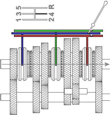
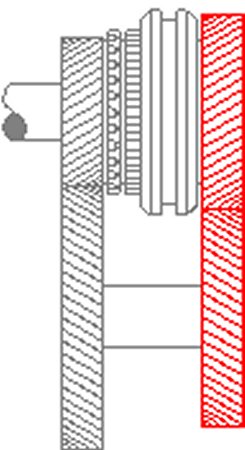
Here is the fourth gear again. It is different from the others because the corresponding gear wheel is not connected to the shaft on which it rotates. This gear wheel is a fixed gear, but in relation to the relatively short input
shaft. Its task is to transmit torque to the countershaft under all circumstances, even in this case where it is not needed at all. This is because the shifting sleeve, which is connected to the output shaft in a rotationally fixed
manner, does nothing other than connect the two shafts to each other.
So, with the H-scheme, you select a specific group of two adjacent gears and can then only choose between these two. However, if the linkage with the shift forks is removed, it is possible to shift two gears at the same
time. Mechanics sometimes use them to lock the shafts in order to carry out certain assembly work.
kfz-tech.de/YGt8
kfz-tech.de/YGt9
|