 Flip-Flop 2 Flip-Flop 2
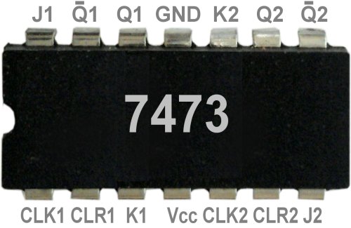
In Part 1, we dealt specifically with the components and wired them to a flip-flop. But there are many and would be too overwhelming for you and us. We are now switching to the more discreet design, for example in the IC
7473, which contains two flip-flops.
This basic electronic circuit is correctly called 'bistable multivibrator'. The adjective implies that there are two states, whereby the outputs are meant here. One with the states 'On' and 'Off' would suffice, but a second one with
exactly the opposite (inverted) state is also lead out.
The decisive factor with such a flip-flop circuit is that the states at the outputs do not necessarily have to be dependent on those at the input, and that is exactly what constitutes the memory effect. Example: If a function is
triggered by pressing a switch once and switched off by pressing it again, the switch must 'know' whether it is currently switched on or off.
So there are two states at the outputs, which can only be changed under certain circumstances, insofar as they are stable, tilting, but by no means accidental. That is why there are always the Set and Reset
wires, although not always directly accessible from outside. It is important here that when one of the two has just developed its effect, it is practically switched off until the other shows effect.
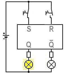
It may be clearer with pictures. Above the complete circuit on the basis of 5V, because of the direct tapping of the flip-flop with energy-saving LEDs. Input S has just switched on the lamp at output Q. At the same time, the
lamp at the Q output is off.
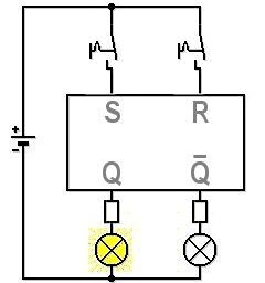
Switching off input S has no effect, which clearly shows the memory effect of the flip-flop. In order to achieve something at the outputs, input R must be switched on. Now both outputs change at the same time. Incidentally, the
input S should remain switched off, otherwise this flip-flop will get into an undefined state.
So, that was the explanation of an RS flip-flop. As you can see at the top of the IC 7473, the two designations Set and Reset do not appear as connections at all. Instead, there are the letters J and K that were once arbitrarily
chosen, which is why we will speak of a JK flip-flop from now on.
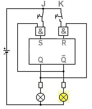
J is connected to S via an AND gate, K through another with R. The second input of the AND gate at J goes to the output Q. So that the switched input J can take effect, the output
Q must be switched off or Q switched on.
The same applies to input K. The only becomes effective when output Q is switched on or Q switched off. The two AND gates included in the circuit ensure that S and R can
never be switched on at the same time.
However, you have now acquired another disadvantage, or is that an advantage? If you look closely, input K or R has won, but input J or S does not have to be satisfied with that, it is free to switch back. This means that the
system could start to oscillate, i.e. it could get back into undefined states.
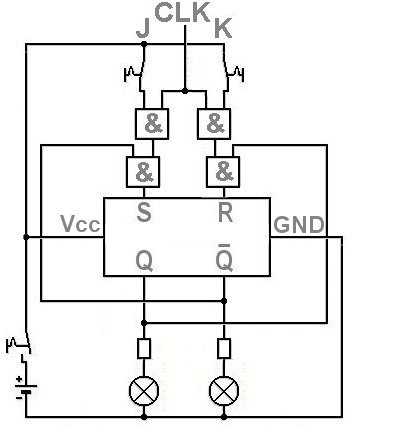
| JK flip-flop completely connected |
This is why the circuit is only available with an additional clock signal. That determines whether the switches are allowed to do anything at all. As usual with a clock, this can oscillate again, but in a controlled process. Apart
from minus (GND) and plus (Vcc) only the explanation for CLR is missing in the picture at the top.
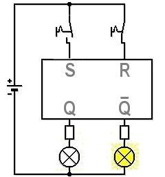
Of course, the last picture with two switched off outputs only appears when the power supply is switched off. When they are switched on, one of the two stable states always results, i.e. one output is switched on and the other
is switched off. Which of the two is uncertain.
|