 Flip-flop 1 Flip-flop 1
At some point a plant must have developed into a living being. Again, there must have been a point in time when this became conscious of him-/herself. Something like that could be transferred to electronics, in this case to
digital electronics. Can that be achieved already by a simple working current relay? But probably not, because in principle it simply passes on a simple switch function.
But when does a circuit start to 'live'? Can it ever develop an awareness of itself at all? Does it mean an independent action when a relay simply reverses a switching function, i.e. 'off' instead of 'on' and vice versa? No, there
must be more behind. It's still a mere takeover.
We have already mentioned such a circuit in the 'Transformer' chapter and are now quite cheekily claiming that the required independence is achieved in the control of classic turn signals, which was traditionally analogue
with earlier hot-wire technology. Why? Because nobody gives the command to blink, how often per minute and for how long the light bulbs should be lit.
How do we come to the circuit shown in connection with the transformer? The basis for this is a so-called RC element, a series connection of capacitor and resistor. While otherwise everything in electronics usually goes
very quickly, there is a delay here due to the charging of the capacitor. This can be set by dimensioning the resistance that limits the charge.
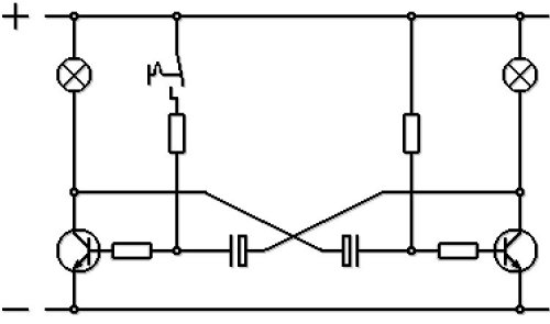
Pay attention to the symmetry of the circuit at the top, only slightly disturbed by the operating current relay at the top left, but this is necessary because the transistor alone cannot switch the enormous currents for several
flashing lights. Replace it with the lamp and omit the left vertical strand. Now the only thing that bothers is the switch, but someone has to start or stop the whole thing.
Actually, the two transistors are not decisive here either, but the respective combination of a resistor with an associated capacitor. The best thing to do is to take a concrete look at the example below. For this purpose, the
above circuit has been simplified so that the left and right side is absolutely the same.
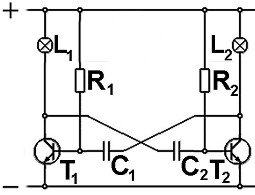
Imagine a voltage of 12V is applied to plus and minus, then the direct connections are via R1 to the base of T1 and those via R2 to the base of T2 decisive. Both are npn
transistors, so they become conductive when at least 0.7V plus are applied to the base. Whether this value has to be reached exactly or is slightly below it, and whether the two resistors are exactly the same, depends on
which transistor switches first.
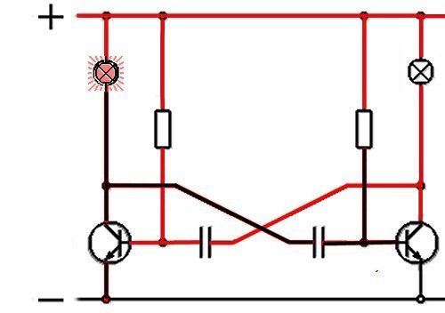
In our example this should be T1. When it switches through, there is hardly any voltage difference between its collector at the top and the emitter at the bottom. The lamp L1 lamp lights up. At the
capacitor C2 there is now minus on the left and plus on the right. Its charging is, however, delayed by the resistor R2. As long as the plus side of C2 does not reach 0.7V, the transistor
T2 remains blocked.
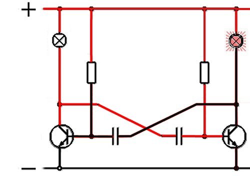
At 0.7V, T2 switches through. At the lamp L2 is now at the bottom minus and at the top plus, it lights up. The capacitor C1 now also has minus on the right and plus on the left. If this
reaches a value of 0.7V, the circuit flips again. After that, however, the charging process is not only limited from 0 to 0.7V, but, for example, if T2 switches through, C1 is charged negatively up to just
under 12V.

What is described here goes far beyond the mere use as an electronic flasher unit. It is an astable flip-flop, not stable because it does not maintain the current state. However, if the capacitors and, above all, the resistors are
designed to be variable, then a Pulse Width Modulation results, with a clean square-wave signal arises. For example, if you want to slow down the electric motor of a fan step by step, nowadays you
don't interpose any electricity-guzzling resistors, but solve the problem by interrupting the supplied current with PWM.
kfz-tech.de/YEl18
|