 Control Control
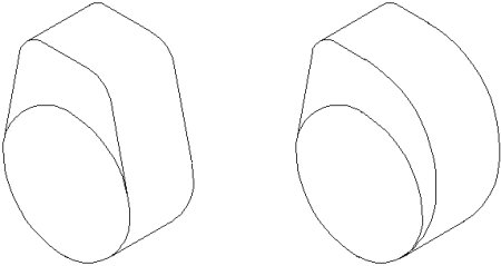
Why are two cams depicted here, of all places, to introduce a chapter on the control of hydromechanical diesel injection? Because a problem the inline pump has with the left cam is very nicely
solved with the right one. What kind of problem? Quite simply: Such an engine could be started with the wrong direction of rotation, e.g. by pushing it in reverse gear.
This is, of course, completely undesirable, not only because of the low engine power, but also because everything that was painstakingly adjusted to before TDC or BDC now takes place after
TDC or BDC. And then the many reverse gears and only one forward gear. Even worse: The oil pump may be sucking oil from the lubrication points and pumping it into the oil sump.
Yes, that couldn't happen to the gasoline engine of that era. It lacked fuel when it sucked in air through the exhaust pipe. And how did one fixed that? The phenomenon of oil leakage was
exploited. This is oil that, instead of being transported upwards to the engine cylinders and injected there, prefers to escape between the pistons of the injection pump and its cylinders and is collected by a leak oil line.
So if you only build up enough pressure in a pump element slowly enough, all the fuel will disappear and nothing will be injected. Therefore, here is one side with the very slow pressure build-
up when the direction of rotation is reversed. By the way, a complete seal between the pump piston and the wall is neither possible nor desirable. After all, lubrication has to come from somewhere, because oil is only
available at the very bottom of the (pump) camshaft chamber.
No matter how we look at it, a diesel engine cannot be left unregulated. Take the inline pump, for example. Sure, the piston pumps fuel toward the nozzle of an engine cylinder. But we mustn't
forget the amount of leakage oil. So imagine the injection quantity is increased. A certain amount of leakage oil is associated with the original speed, because this depends on the time the
injected fuel is under high pressure.
What happens when the injection quantity increases? Of course, the engine speed also increases, which means less time for leakage oil to drain away. So the injection quantity and thus the
engine speed increase further, which in turn reduces the amount of leakage oil. This game can be continued for a very long time, until the diesel engine has long since reached nirvana in
terms of engine speed, often without even a chance of rebirth because too much has been damaged.
kfz-tech.de/PDM31
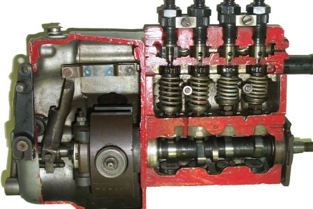
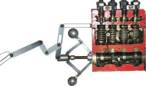
Here's a cutaway of the older A-pump, with the individual pump elements on the right. The one on the far left is even visibly cut open in the enlarged image, so you can get an idea of how
small a pump piston actually is. Below is the camshaft, on which roller tappets move up and down. The lower chamber contains oil, above it air, and the upper chamber is filled with vented and
filtered fuel.
| Same ratio to the control rod with little and much gas |
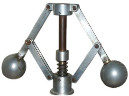
The area on the left also contains air. The flyweights in the lower right corner of this space are rotated so that the springs are visible. Actually, only one, the one for controlling the final speed,
is visible. But there's a second one underneath for idle. In principle, this results in three positions: fully compressed when stationary, slightly extended when idling and between actuated idling
spring and non-actuated final speed spring.
| Different ratio to the control rod with little and much gas |
The latter, by the way, can be adjusted. The housing has corresponding openings for this. The diesel engine was actually relatively easy to tune; the more powerful it was, the more it tended
to produce soot due to the lack of excess air. Watch tractor pulling with similarly modified engines, and you'll see what I mean.
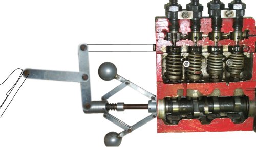
Now, however, a connection to the accelerator pedal is needed, as well as one to the pump elements. You can see the latter above, which can be moved horizontally into the middle space on
the right. This rotates the elements. This can be either the small pistons or the surrounding cylinders, which usually have two bores. In any case, the rotation must not impede the stroke
movement of the pistons through the camshaft.
So there are four clamping rings with a toothing and this meshes with the so-called control rod. It should go out to the left towards full throttle and in to the right towards idling. And now to the
accelerator pedal, which engages on the far left of the upwardly deflected lever, or more precisely, on the inner part of a ball joint. When accelerating, the lever pivots to the left, meaning it's
pulled.
The assembly of the throttle lever, flyweights, and control rod is somewhat complicated, as the connection is not just a rod, but a slotted tube. The arm, located on the shaft leading to the
throttle lever, moves up and down with a thickened section in the slotted tube. This allows it to essentially pull the slotted tube to the left and additionally move the pivot point toward the center.
So if there is a need for control at idle or at maximum speed, the control rod and flyweights work against each other. As they open, the flyweights pull the control rod back. However, since the
pivot point of the slotted connecting tube is far down at idle, the flyweights have a significant influence on the idle speed. If you listen to an old truck idling, you can recognize the centrifugal
governor's work by the regularly rising and falling noise.
The situation is different when it comes to controlling the final engine speed. The high pivot point allows for much more sensitive throttle control. This is due, among other things, to the already
large injection quantities. The engine isn't supposed to slow the vehicle when reaching the final engine speed, but rather allow the achieved injection quantity to be maintained.
You can see what one of the first controls on the injection pump can already achieve. And what is now being tested or adjusted on the injection pump test bench? This is the most equal injection quantity possible into each
cylinder at each of the four clamping rings. In addition, there are the lock nuts visible under the springs, which are intended to ensure an exact 90-degree clearance relative to the camshaft visible here.
kfz-tech.de/PDM32
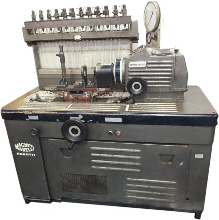
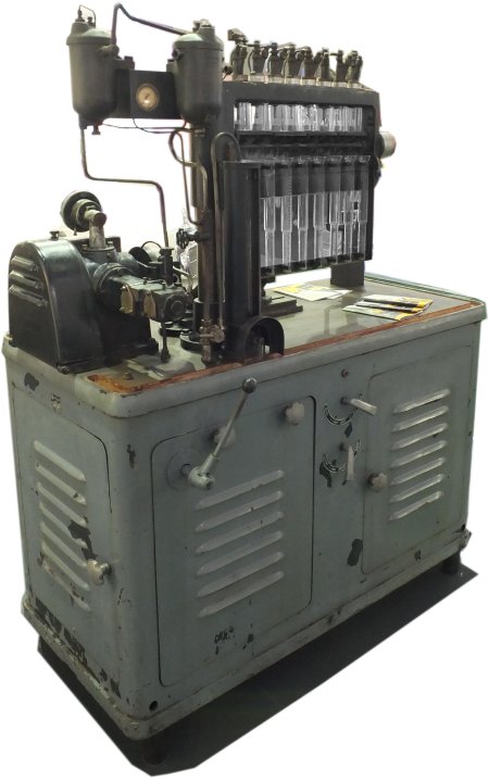
Test benches for injection pumps have been around for a long time; here are two from Magnet Marelli. The one below dates back to the 1940s.
kfz-tech.de/PDM33
|