 Glow 2 Glow 2
When replacing glow plugs, you can hear it from far away: extreme caution is required to ensure that none of them break off. How can you protect yourself from this? The first rule is: Only attempt removal when
the engine is at operating temperature. Even greater caution is exercised when the torque limitation, which is otherwise only used for tightening screws, is also used for loosening them.
If this method has not been successful, perhaps some oil or a chemically even more suitable substance (WD 40) can help, which you drive around in the bores of the glow plugs for days. This may cause a
short circuit. Then you either use less of the substance or do without preheating for a short time, which is probably relatively easy in summer. However, consider the consequences already mentioned in the
previous chapter.
Of course, it's no use. After enough attempts, you have to increase the loosening torque and now risk breaking it for good. Because driving or starting with only one glow plug less is not only no fun, it can also
be prosecuted if a law enforcement officer notices the illuminated MIL light. And you certainly won't pass the general inspection.
Once the mishap has happened, it becomes a sweaty business. Not because so many calories are needed for the work ahead. That may be true, but it's more likely the fear of the
costs for (dis)assembling the cylinder head and reprocessing it, if that's even possible and a new one isn't needed. However, household remedies such as a left-hand twist drill or extractor will not help here.
Because the part that is usually broken off between the hexagon and the thread (picture above) can be very tight, you need a special tool kit designed for this purpose. First of all, this is a kind of double drill
with a small diameter at the very front, a larger one behind it, and a stop. The aim is after removing the inner coil, at the same time to remove the outer thread of the glow plug, leaving the inner thread as
undamaged as possible. Then drill into the next sleeve below, using the appropriate guides for the hand drill.
So, instead of trying to unscrew the rest of the glow plug using its thread by clamping and turning it to the left, you remove enough material so that only the sleeve and the filament remain. Then cut a
sufficiently long thread into the sleeve and screw in a pin with a right-hand thread from the tool set. This is then pulled out of its external thread with the force of a nut.
Even this is still a problem with some particularly stubborn glow plugs, which is understandable given how much resistance they offer. Given the price of glow plugs and the risk involved in removing them, it
may be wise to replace them all as soon as the first one fails, or even earlier. Of course, if the glow plug is still intact, you should not take the risk of carrying out the repair described above, but you can protect
yourself from this by attempting to loosen the plug with a carefully calculated torque.
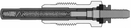
Here is another cross-sectional view of the glow plug, showing the combination of two coils on the left, the glow tube surrounding them, and the connection to the plug connector on the right, shown slightly
shortened. The glow tube is formed by a metal sleeve that must be resistant to heat. Since it is connected to ground via the screw connection of the glow plug, it may only be connected to the coil at the left
end. A powder made of magnesium oxide, for example, protects against vibrations of the filament and possible short circuits.
More difficult to describe is the glow plug's ability to regulate itself. First of all, there is the heating coil on the far left. Only it protrudes into the combustion chamber and its resistance is largely independent of temperature.
The control coil to the right of it is completely different. Their resistance increases significantly with temperature, so that the current consumption of the combination of both coils decreases slightly precisely when ignition
occurs in the combustion chamber.
The preheating process therefore begins with a very high current and temperatures of over 1000°C at the heating coil. With a slight delay, this heating also affects the control coil, which then reduces the current flow. This
means that the high temperature is largely maintained, decreasing slightly rather than increasing further.
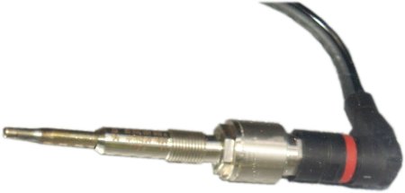
This is now a special glow plug with three additional connections: power supply, ground, and signal line. It therefore also acts as a sensor, recording the pressure in the combustion chamber via a membrane in the head,
converting it into an electrical signal, and sending it to its control unit. In addition to the pressure level of up to 200 bar, the timing of the pressure development is also very important.
An example of the benefit of such a measurement would be the pressure during combustion of the injected fuel. Here, aging can cause leaks in the individual combustion chambers. In order to compensate for these
differences in the amount of fuel injected to ensure a uniform load on the crankshaft, the differences must first be identified and their correction made verifiable.
Unless they are switched off directly by start-stop, modern diesel engines switch to an extra-low idle speed. This is only possible if extreme care is taken to ensure that the pressure formation is evenly. Even if there is only
a minor malfunction, even a layman will notice it immediately due to slight shaking of the engine. In addition, such a system can also improve cold starts and cold running.
However, the injectors are still divided into classes. This shows the limitations of such a regulation due to different injection times. This probably also applies to certain lower fuel qualities. Creating pressure conditions that
are as uniform as possible between the individual combustion chambers naturally also affects the exhaust gases via raw emissions. Allegedly, this even made it possible to achieve Euro 6 without costly post-treatment of
nitrogen oxides.
Finally, that's one of the few possible measures that has a positive effect on both nitrogen oxides and carbon dioxide by helping both to reduce more. The effect on easier fault detection by the workshop is easy to see.
However, the actual cause of the compression leak is not immediately apparent in this system. But it can reduce costs by dispensing with, for example, the knock sensor, which is now also found in diesel engines, and
even the air mass meter.
|