 Dual circuit brake valve Dual circuit brake valve
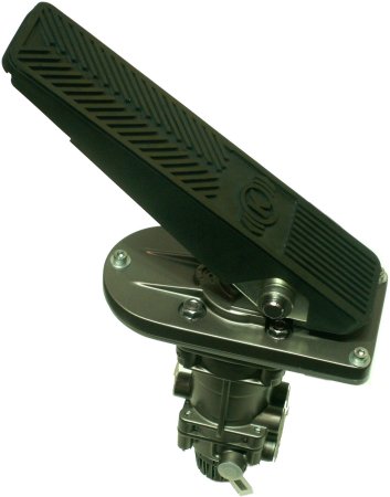
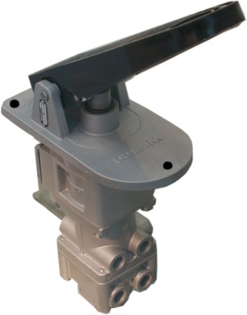
There is probably no other component whose movement options are prescribed as precisely as the dual-circuit brake valve. In the version above it is also called a treadle operated valve. The fact that there is also a version
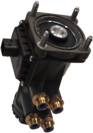
only with a plunger (picture below), i.e. without the upper part, and therefore it does not always have to be embedded in the floor of the driver's cab, is not that important for the function.
Why is its activity regulated so precisely? Because compressed air up to, say, 8 bar can be used here. But that would be a full braking and that is only needed in the rarest of cases. Partial braking is the rule and comes in a
wide variety of shades. The driver should by no means have the feeling that the vehicle is doing whatever it wants.
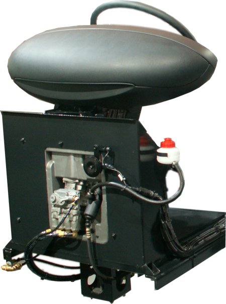
| Driver's seat of a bus seen from the front |
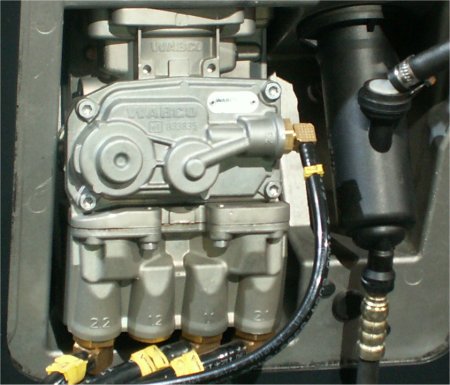
For example: Wabco prescribes for maintenance, during which the behavior of this brake valve is checked, that an effect can already be seen after a maximum of 0.4 bar and that this effect must gradually increase slightly
after each maximum of 0.3 bar. The pressure difference between the outputs to the two brake circuits must not exceed 0.5 bar.
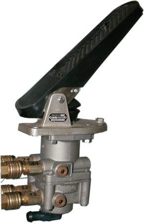
The four connections are indicated here. At the front the supply lines come from the two foot brake circuits (1st digit: 1), at the rear they go to the two axles (first digit: 2). At the very bottom the bleed from the two brake circuits
when the pedal is taken back. This hisses a bit, but usually not as loudly as the excess pressure used to blow off at the pressure regulator.
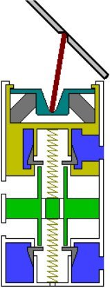
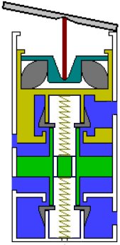
Here you can now see a simplified drawing of the inner workings of the brake valve. You can see the connections of the brake circuits 1 above and 2 below, the inputs on the right and the outputs on the left. In between there
is a so-called weighing piston, which ensures a maximum pressure difference of 0.5 bar. As you can see in this driving position, the full pressure comes from the right.
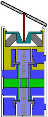
At the first moment when the pedal is pressed even relatively lightly, it looks as shown in the picture. The plunger pushes the piston down. The part, which is drawn at different angles on the left and right, is made of (hard)
rubber, which means that it is connected to the reaction piston surrounding it. All the parts mentioned so far have now moved down a bit.
Please compare the two drawings again and note that the weighing piston in the middle no longer has any distances at the top and bottom. It even opened the connections to the pressure rooms upstairs and downstairs.
For a brief moment, the full pressure from above and below acts on the weighing piston, which, as a result of this and because of the two springs at the top and bottom, assumes a middle position.
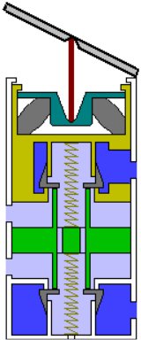
Here the moment is over again, because the pressure, which is far too high for this pedal position, has affected the reaction piston from below and compressed the rubber. The reaction piston is now almost in the driving
position again. So every time you press the pedal, a certain amount of high pressure comes into the output lines. How long depends on how hard you press the pedal.
And exactly the time until the reaction piston returns to the top again also determines the pressure that from now on acts on the brake cylinders. If the pedal is released, the small distances above and below the weighing
piston are created again and the pressure from both brake circuits can escape downwards through the center and thus outwards.
Hopefully full braking is rarely necessary. The pedal was pushed down so hard that the rubber could no longer compensate. It is therefore responsible for the fine dosage of pedal travel and output pressure. But now the full
pressure act on the wheel brakes.
kfz-tech.de/YDB5
|