 Multi-circuit protection valve Multi-circuit protection valve
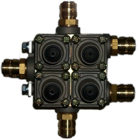
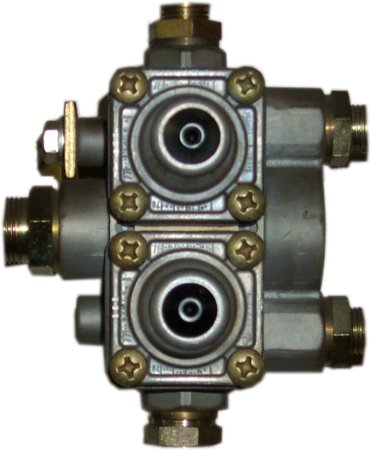
There are different numbers of circuits that such a valve can protect (from each other). The picture below shows a two-circuit protection valve, for example. We are dealing here with the most common, the four-
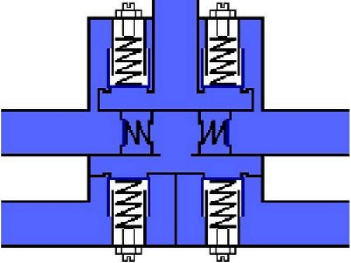
circuit protection valve (picture above).
| Here the arrangement of a four-circuit protection valve to the air tanks. |

The individual connections are labeled in the image below. 21 and 22 belong to the two circuits of the service brake. 23 leads to the parking brake (handbrake) and 24 to the auxiliary consumers.
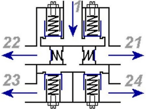
It is best to assume that the system is not under pressure. As soon as the compressor is running, pressure enters into the four-circuit protection valve from above via connection 1. Nothing happens inside at first
because a total of four back-pressure valves with springs pre-tensioned by adjusting screws do not allow the flow to continue.

Springs and screws are set so that the two upper overflow valves open first, simultaneously or one after the other. This means that brake circuits 1 and 2 are supplied with pressure first. Meanwhile, the brake
circuits with the auxiliary consumers and the parking brake still have to wait. In the latter case, the spring accumulators on the rear brake remain activated as long as brake circuits 1 and 2 do not yet have
enough pressure to drive off safely.
Both valves are shown above in the open state. It is important to note that the pressure after opening hits a larger area than before, meaning it can work more effectively against the force of the respective spring.
The pressure to keep the valves open is therefore lower than the opening pressure. It gradually rises in the lines to the brake circuits to the level of the pressure flowing in at 1.
The two check valves in the middle have two functions: firstly, each of the two brake circuits for the service brake can supply the auxiliary consumers and especially the parking brake with pressure.
Nevertheless, it remains impossible for one of the two to lose pressure to the other.
Result above: The pressure on the left first opened the respective check valve and then, as it continued to rise, the overflow valves at outlets 23 and 24. The former gives the spring in the spring accumulator
counterpressure, enough for the truck to drive off sometime. Not shown here are throttles (narrowings) behind the overflow valves at 23 and 24, which prevent excessive consumption in the respective circuit and
thus too much pressure drop in the others.
As long as the pressure loss can be compensated by the compressor in the event of a leak in one of the circuits, nothing happens in the four-circuit protection valve. If the loss increases beyond this but the
pressure only drops slowly, the respective overflow valve closes when the force of this pressure acting on the effective area of ??the valve plate becomes less than that of the closing spring.
A very rapid loss of pressure means that a lot of air flows through the ring surface of the open overflow valve, which therefore acts as a throttle. The uniform column of air under the valve plate is therefore
continuously reduced, at least at the edges. This is referred to as dynamic closing pressure. Now it is easier for the spring to close the valve than with static closing pressure.
If one of the circuits loses a large amount of compressed air, these findings lead us to perceive that only those valves remain open where there is no pressure drop. Only the affected circuit is closed, thus
protecting the others against pressure loss.
|