|
|
 Troubleshooting Low-Speed Troubleshooting Low-Speed
Diagnosis reports an error in the low-speed bus. In contrast to the high speed, in most cases the error would not be noticed at all. Again a reason, from time at times, and especially during inspections, to make a diagnosis
and not to let the driver go with a possible defect. We also leave open whether or not the fault is reported to the driver itself.
This means that the bus should be obvious, e.g. the one responsible for comfort. Now we are also heartily indifferent to the topology. We just want to get the two data lines somewhere. Conciliatory proposal: two lines going
to one door. You would have to prick them, not so elegant, maybe there is a plug connection at a column, e.g. in the middle, at the bottom (circuit diagram).
By the way, it is not always necessary to buy the complete circuit diagram. Many manufacturers now offer as a special service the view into their full workshop programme from a single-digit hourly price. It is then
advisable to pre-configure the computer with an empty new directory and to scoop over as much as possible, if necessary by pressing the screenshot button and Ctrl-V into a graphics program. You can sort and reassemble
them afterwards.
So, what do we have now? Two data lines and ground, the vehicle ground should be enough, but if we get the two data lines, so much the better. Unfortunately we still have to deal with a multimeter, because oscilloscopes,
although equipped with beautiful screens, have not yet become the standard for measuring, but often just stand around. This is now no arrogance, but would simply go faster.
No, not the keeping at the pins, but the evaluation. Now it's a matter of squeaky-clean logic. Question: Are we even at a damaged bus? Well, first one, then the other data line against minus. What do we expect? At least
not voltages at one significantly above the middle between 1.4 and 5 V and at the other significantly below the middle between 0 and 3.4 V. If this is the case, then everything is fine here. We would of course be able to see
this much better with the oscilloscope on the basis of the data packets.
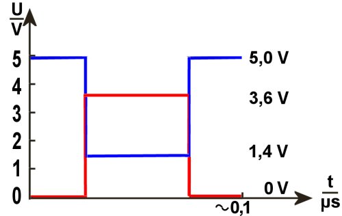
Why clearly above or below the middle? Such a multimeter can only display an average value of all voltages. If the voltage at CAN high would constantly oscillate between 0 (recessive) and 3.6 V (dominant),
1.8 V should actually be displayed, but only if the dominant and recessive states alternate at the same time. But they do not. Even if this were the case during a data block, there would be still the time in between. And in that
time CAN high is recessive, i.e. at zero. That pulls the average value down strongly from the middle. With CAN-Low it is exactly the other way round.
In order to save time, we do not want to know now whether a line is terminated to earth or plus or whether there is a connection between the two lines, because we only have to make sure in what direction we need to test. It
is a question of whether the error is to be sought in one direction or another. However, we remain, whether multimeter or oscilloscope, at passive measurement. This expressly does not include a continuity test, which can
lead to destruction.
We continue with the multimeter. If all we did was pricking, then it takes its revenge now.. But if we have a tester at our disposal we are saved for now. Once again briefly to the repetition: We are in single-wire operation. So
everything should still work. Now we do something with the still intact data line to disturb its function, to the other, to ground or connect to Plus, no matter. Now the tester should show us which control unit(s) we have
disabled.
Unbelievable, but true, the two data lines can be mixed up, of course due to improper interventions afterwards. If the sloppiness of not querying the error memory is added, the error cannot be related to the work carried out.
So work from separation point to separation point again. Such a mix-up is hardly different to than the errors mentioned so far.
We can close here, because either lines are affected, in which case we don't want to make a decision now whether to find and repair the exact spot, or to replace the line (by an additional). Or it could be a control unit, also a
question of classic workshop work. In any case, defective connectors or such with contact resistances belong to the category of Line repair. Make sure to delete any errors at the end.
| English subtitles are possible . . . |
|
|