|
| 
|
 Autonomous - E-Motor Autonomous - E-Motor
Electric power for rotational motion and torque with the highest possible efficiency, that is the purpose of electric motors. This is where the laws of (electro)magnetism come into
play. Generators also work on similar principles. In the automotive sector, machines that can switch between the two operating modes are becoming increasingly common.
The energy stored through regenerative braking provides the capacity for an additional boost to the hybrid powertrain, for example, for a better acceleration and/or a more fuel-efficient internal combustion
engine. This way, the overall efficiency can also be improved outside of stop-and-go traffic. Technically, a generator is defined as a device in which rotational speed and torque are directed against each other, in
quadrants II and IV of the torque-speed diagram. If the direction is the same, it is one motor, quadrants I and III.
There are also plenty of motors available for home use that run at a constant speed on the 50-Hz power grid, with their torque and rotation speed adjusted by single-stage gearboxes. To
drive a vehicle, of course, you need electric motors with variable rotation speeds. In theory, this could be regulated by comparing the setpoint and actual values, or it could simply be controlled. that is, without
monitoring the final rotation speed achieved. Only the former are suitable for use as automotive powertrains.
If the speed needs to be maintained with a high degree of precision, we usually refer to a servo drive. Depending on its position, even the motor can be controlled; for example, when activated, it continues to
rotate by exactly specified degrees. There is no such need when it comes to vehicle propulsion. Nevertheless, sensors are necessary, particularly for temperature measurement, which is crucial, for example,
for performance limitation or, in other cases, for a boost function. Otherwise, the current intake can also be sensed.
Electric vehicle motors rarely have a direct drive. Even when used as wheel hub motors, they are available with or without a transmission. The former generally applies to all other
installation locations. Mechanical transmission elements can, for example, enable the engine to operate primarily under economical conditions and also provide a certain degree of
flexibility. In addition, any clutch that may be used can compensate for minor axial misalignment and disconnect the motor from the drive.
Provided that the rotational speeds are not too high, the cost of an electric drive depends on the required torque, that is, primarily on the length and/or diameter. The current requirement depends on the
operating voltage. That will also determine the size of the inverter, for example. In addition to the rotational speed requirements for the electric motor, the torque can be designed for either efficiency or
performance.
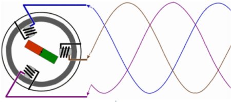
Two types of three-phase motors are suitable for powering motor vehicles. First, we’ll take a look at the synchronous motor, of which there’s already a schematic diagram above. As rotor, we see a permanent
magnet that is driven by three-phase electric coils. Whenever it reaches the ideal state of its north pole relative to the electrically generated south pole, or its south pole relative to the electrically generated
north pole, the polarity changes.
It’s a bit like luring a dog through the apartment with a sausage. The dog will only keep running after it as long as it can't quite reach the sausage. Once it has it, it sees no reason to
move. However, there is probably also a point at which it might lose interest and stop if the distance to the sausage becomes too great and it no longer sees a chance of success.
Something similar happens in a synchronous motor as well. In fact, when we demand torque from it, the angle between, for example, its north pole and the nearest electrically generated south pole
becomes larger and larger. If this angle exceeds 90°, the rotor comes to a stop or moves only with slight jerks. In any case, it no longer delivers any usable torque.
Of course, a motor like this, which operates on a three-phase power grid, cannot be used in a motor vehicle. First of all, these three phases, which are usually essentially delivered right to the door, must first
be generated here from the DC voltage of a high-voltage battery; and second, they must under no circumstances be operated at a constant frequency, because we naturally need varying speeds.
If we consider the change in polarity across the three phases as a kind of predetermined speed, then the rotor follows it exactly. It does not overtake; its distance, expressed as an angle, actually increases
with increased torque output. The frequency conversion,which, by the way, also allows for reverse operation, is controlled by an inverter. Its size depends on the maximum current draw of the motor. This could
involve modern power electronics, or individual functions could be generated mechanically using a rotary mechanism similar to that of a motor.

Here the inverter (top left) and motor (bottom right) on a Tesla Model S
A short-circuit cage consists of ladder bars arranged parallel to the rotor axle, the ends of which always terminate in the same two short-circuit rings. To simplify things, you could also
select two opposite ladder bars and connect them together at one end. Below, this loop of wire, open at the other end, has been fitted into a permanent magnet in such a way
that it can rotate.

Now you might think that everything is just as before: you could tap a voltage at the ends of the rotating conductor loop to create a generator, or you could connect it to a voltage source
to create a motor. That's not the case, because then we would need a mechanical connection between the loop ends and the outside, and the asynchronous motor discussed here
doesn't have one.
We modify the experimental setup and short-circuit the conductor loop, that is, we connect the two ends together. When we rotate the outer permanent magnet now, we naturally mean
a rotation of the outer magnetic field caused by a phase shift, just as was described for the synchronous motor. As long as the inner conductor loop is not rotating, a voltage is induced here
just as if it were rotating and the external magnetic field were stationary.
Thus, the magnetic field generated by the stator induces electricity in the rotor’s conductor loop, magnetizing the rotor so that it can support itself against the external magnetic field, and
a torque is generated. Of course, the control of the electromagnetic rotor must be different from that of a synchronous motor. With a simple three-phase sinusoidal voltage, nothing would happen at all.
Now let’s shift our focus to the operating data and examine the difference between the two engine types from a different angle.
We will examine the nameplates of a synchronous motor and an asynchronous motor. However, these aren't car engines; they just happen to run at the same rotation speed. 50 hertz, or 50
oscillations per second, is equivalent to 3,000 per minute. That would be the rotational speed for a single pole pair. The motor below has 4 pole pairs, so it would run at 750 rpm at 50 Hz.
For a synchronous motor, we expect the nameplate to indicate the corresponding rotational speed, because even though the rotor lags behind the rotating magnetic field by a certain angle (less than 90°)
when under load, it still maintains the same rotational speed. And that is exactly what sets the asynchronous motor apart. The nameplate would indicate a slightly lower speed than 750 rpm, for example, a
good 3 percent lower. And that is exactly how you would recognize an asynchronous motor just by looking at the nameplate.
Unfortunately, this insight isn't very useful for our vehicle engines, but it does explain part of the difference between the two types of engines. It goes even further, because in an
asynchronous motor, the magnetic field must actually overtake the stator. That’s also where the name comes from, of course. Only in this way can the induction described above take effect in the conductor
bars, and thus the magnetism required to drive the rotor. Unlike in synchronous motors, this non-constant deviation is also referred to as 'slip', which in the above case is slightly over 3 percent.

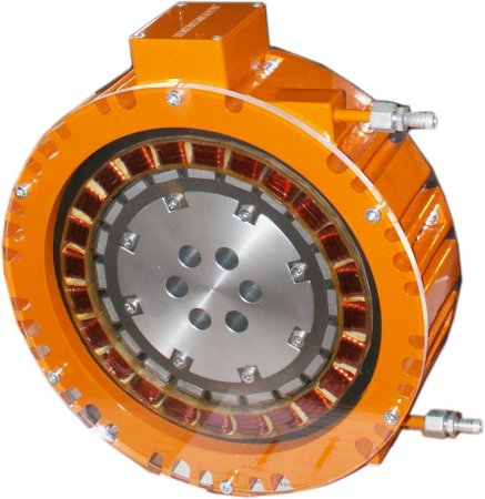
Just as with a commutator motor, a single conductor loop is not sufficient. Above, you can see a copper cage like the one integrated into the rotor of an induction motor. The number
of conductor loops is significantly greater than that of the bars, because each bar can be part of more than one conductor loop. Incidentally, unlike a synchronous motor, there is no 90° limit
between the rotor and the external rotating field when the motor is subjected to excessive torque.
|
|