|
|
Two-stage Turbocharging

Function
Putting two chargers in series increases the torque for low and high numbers of revolution.The response time is decreased, too, but their might be small disadvantages for medium numbers of revolution. The idea for
two chargers stems from racing. It helps in fulfilling the emission law, Euro 4.

How it works
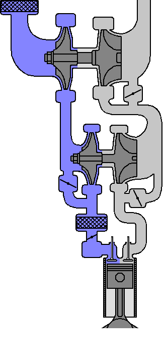
The picture above displays a bunch of complex pipes, it helps to click on the diagram first.Back to the view. The filtered fresh air enters via the black plastic pipe above to the right. It flows downwards behind the
aluminum bend into the middle of the large charger. It returns centrifugal into the thick, half cut pipe, and may flow directly to the below right, or first through the small charger. This depends on the position of the flap in
the pipe.The flow continues - outside of this view - to the charge air intercooler and the inlet valves.
The exhaust manifold is visible on this side of the engine. It has a direct connection with the tangential entry of
the small charger, and via a valve with the (tangential, too) entry of the large charger. Additionally, there is a barely visible direct connection between both chargers. From the large charger the exhaust gases flow to the
temperature sensor and the broad-band lambda oxygen sensor towards the catalyst.
Both chargers may be surpassed. Pneumatically operating,
electrically controlled flap
shifts determine how much air is going through the charger, and how much is surpassing it. Just the fresh air is always directed through the large charger. The flaps are controlled by the engine control unit. For lower
numbers of revolution, mostly both chargers are operative. The higher the engine speed, the less active the small charger becomes.
|
|