|
|
Mechanical Petrol Injection Pump

Assignment
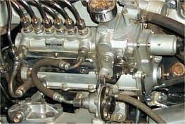
If old-timers are equipped with this type of pump, it becomes somewhat more expensive, simply because there are only a few specialists who know a lot about it. The petrol fuel injection pump has for a long time
influenced the performance behaviour of Otto engines. First of all, in 1951 for the two-stroke engine, and then in 1954, beginning with the direct injection of
the 3 litre Mercedes engine.
Then, and on numerous other occasions, the pump has had an influence on racing events, at that time however, with indirect injection. In the meantime the Bosch company has received one more competitor, the
Kugelfischer company. Until to the appearance of the first electronic fuel injection systems, both offered the only alternative to carburetor systems.


Function
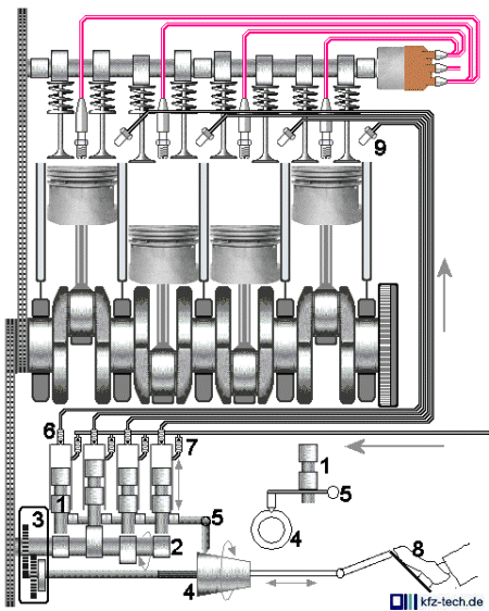
The above illustration shows injector-valves (9) which, in the diesel engine, are wrongly called nozzles. As with its in-line pump, one injector per
cylinder is also used.
However, these do not spray directly into the main combustion- or side chamber, but - as it still is today - into the inlet manifold shortly before the intake valve. Each valve has its own pump element with piston (1)
which is driven by one cam of the camshaft (2). This can be driven by the crank- or the camshaft, it only runs however, at half the crankshaft RPM.
The springs on the piston were omitted for better clarity. Of the two check valves per pump element, one is installed in the fuel intake, (7) and one with opposite effective direction at the beginning of the pressure pipe
(6).
At this point the regulation becomes somewhat complicated. Normally the accelerator pedal is connected with the throttle valve. It's the same here. In addition however, the fuel injection pump also needs information
about the position of the throttle valve, so that it can always inject the proportionate amount of fuel according to the volume of the intake air. Therefore, a leverage with which a round, horizontally mounted on a shaft,
truncated cone, which can be shifted back and forth, is illustrated here. Through this cone a tracer-pin mounted above it, is lowered or raised. This, on the other hand, turns another shaft (5) in such a way that, e.g.,
during idling, the single pump plungers can no longer return to their lowest position. They pause somewhere around the middle of the stroke, or even higher, and supply accordingly, the following strokes with less.
The cone with its tracer-pin and the shaft is also shown from a different perspective.(5)
This however, is not enough. It would still be possible to put your foot down hard, although the engine , e.g., on an uphill, strains against the load. It would then remain in a low RPM area, and would get a mixture which
is too rich. Therefore, the engine speed is also taken mechanically into the regulation. The component (3) in the principle sketch, is responsible for this. Here, with rising engine speed, the shaft with the cone is turned
more strongly against a coil spring. The cone is not uniformly round and it raises the tracer-pin even when the accelerator pedal position is the same and the engine speed is rising. It depends entirely, on how it has
been ground. It fits, as a rule, only to one certain engine. In Kugelfischer systems an additional spacing cam, which can be shifted in two directions, is used.
The injection pressure of almost 40 bar is also higher here, compared with approx. 25 bar with Bosch equipment. The system is also equipped with warm-up and cold start regulations, which are carried out later by
an electrically controlled magnetic valve. This way, the engine can be operated, if needs be, also with other defective equipment.
|
|