
|
(E-) Magnetism 3
The moving-magnet speedometer measures the speed by transferring the rotary movement of a flexible shaft to the speedometer needle of a permanent display. Thereby, the swing of the needle, pulling against a
return-spring, increases according to the rising rotation speed of the speedo-cable.
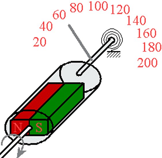
The flexible speedo-shaft coming out from the gearbox is connected to a small bar-magnet. In the above drawing it is shown in red for the north pole and green for the south. It rotates in an, also revolving, aluminium
drum. According to Heinrich Lenz's (1834) law of magnetics, the rotating magnet in the aluminium drum induces eddy-currents, which become stronger with the increasing rotation speed. What happens is, the bar
magnet attempts to transfer it's rotary movement to the aluminium drum, the faster it turns the more it tries to transfer. Thus, the drum rotates against a spring at the end of the shaft when the rotation speed of the
speedometer cable increases. This again, strengthens the swing of speedo-needle, which is also linked with the aluminium drum. This then, indicates the respective speed.
Mechanical speedo-cables generally, are given their rotation speed from the gearbox output or directly from a non-driven wheel. There have also been occasional speedometers which worked on the principle of the centrifugal force regulator. Modern speedometers however, are almost exclusively electronic. One or more reed-contacts are excited by an encircling magnet to cause a switching.
The developing impulses are evaluated through a circuit in the speedo or through the engine control device, from there they are transferred analogously to a stepping-motor or to a digital unit (Kadett GSI, see above
picture). In the meantime, the generation of reed-contacts has has been replaced by sensors which have even less physical contact. .
Although there have been, and still are, numerous attemps to replace the speedo-needle, it has managed to assert itself, even into the computer-era. In the meantime in fact, the needle is even simulated in some
displays. Apparently, people are better able to percieve them quickly and with less concentration than is required when one has a continuously changing number in the display. 10/12
|
|