| Operation of the fuel delivery pump |
Function
Already Rudolf Diesel had the idea as sketches from the time of the development of the first diesel engine prove. Indeed, fittings up
to 1/10000 mm were impossible at that time. Generally there still was no hydraulic injection. The world had to wait another 30 years for the first fuel injection pump and another 30 up to the first engine with pump nozzle.
But also these were introduced via the ship diesel slowly in the truck area and it lasted once again 40 years, until also small diesel engines were equipped with this technology. The predecessors of these engines
were direct fuel injections with distributor type injection pump and they were indeed powerful in terms of torque particularly in the force-intensive lower speed range. With the pump nozzle another clear increase
was possible. This is almost equally valid for engines with Common Rail. Thus a 2 litre engine with supercharging
with revs less than 2000 1 / min manages a torque of more than 300 Nm. These are values a similar petrol engine cannot provide at the moment.
How it works
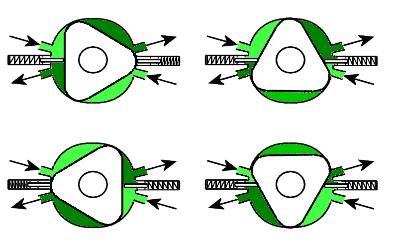
Already with low revs fuel must be extracted from the tank to be delivered to the pump nozzle elements. A vane-type pump does this. You can see from the scheme in the figure on top that a displacement compressor
with (in this case) three cams rotates. Against its cylinder two spaces are separated on top and below by two locking cams which work due to springs on the left and on the right against the displacement compressor.
Two pipes each flow into both hydraulically separated spaces. At the beginning a cam passes by the inlet pipe and increases the pump space. It would drag around the sucked fuel amount on and on in front if it was
not for the locking cam which makes it deliver the fuel to the pressure pipe and subsequently to the pump nozzles.
The distributor pipe (figure 3) is a book with seven seals. If you watch closer, you see below a thicker pipe for the flow, and on top a thinner pipe for the runback. Here a mixture occurs through a pipe-in-pipe-design and
suitable openings between fuel anew from the fuel pump and fuel returning from the respective pump nozzle. This is hotter. It is important in the whole process that every cylinder receives fuel of the same temperature.
With fuel injection pumps this could reach approx. 80°C, here up to 120°C. If the temperatures differed, this would also be the case for the injection amounts. The high temperature is also the reason for the cooling of
the fuel in the runback.
Of course, not always a distributor pipe is required. Most of the pump elements are supplied through a hole in the cylinder head. Another takes over the return. Diesel fuel, taken up by the injectors, is then also filtered a
bit.