|
|
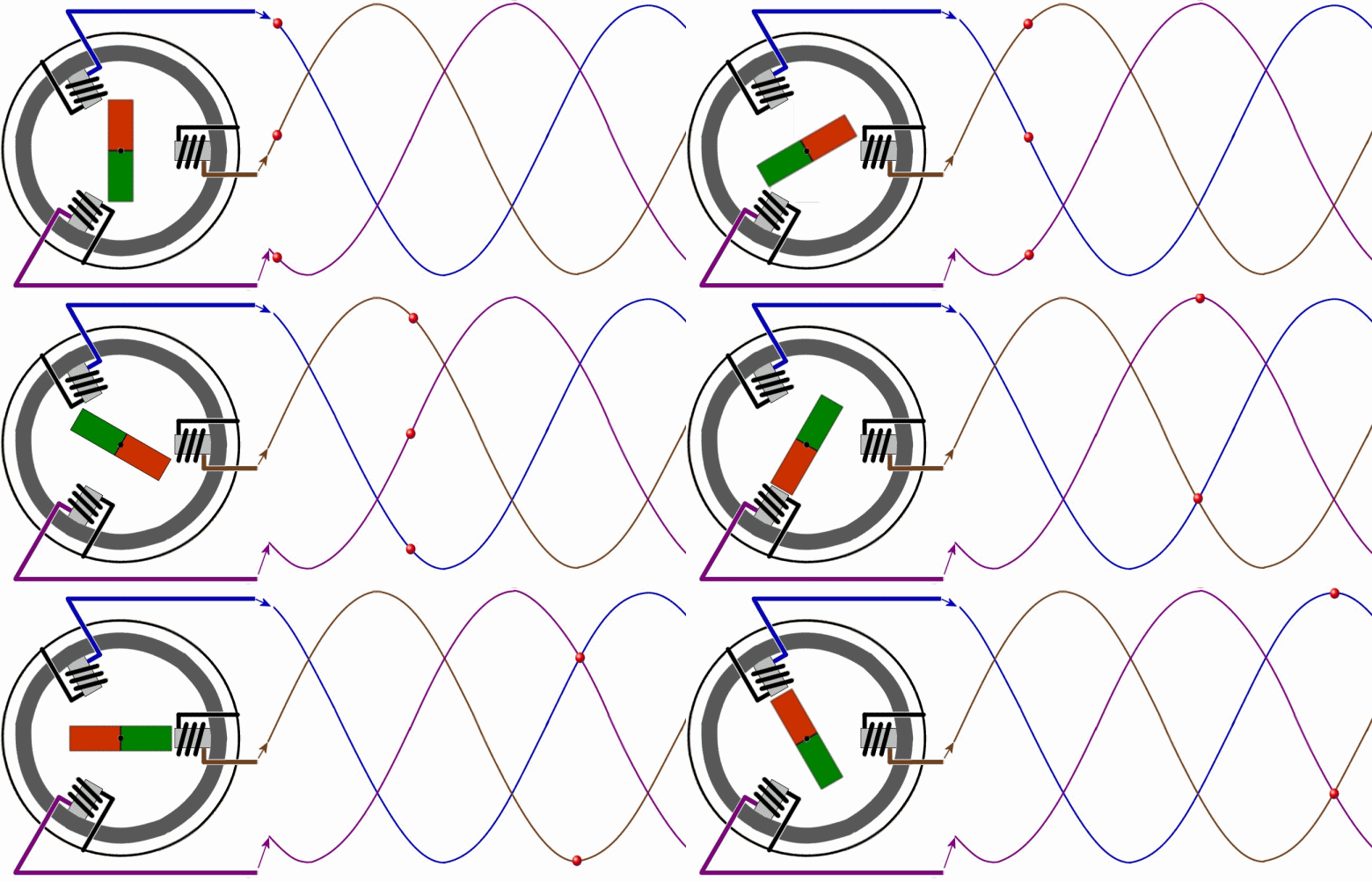
Alternator (phase voltage)
| Simplified view of the procedure |

| Alternating Current, from where the AC generator get it's name. |
Here the generator builds up differing voltages in the individual strands U (blue), V (brown) and W (pink). In the animation which, by the way, can be enlarged, we assume, very simply speaking, that it is a rotating
permanent magnet. Thus, in this case, the strength of the magnetic field cannot be influenced by a voltage regulator as is the case in reality.
Whenever the south-pole (green) passes a coil, the here induced tension reaches its minimum, with the north-pole, it maximizes. Because the three stator-windings here are each offset by 120°, the following voltage
profile hastens up from the rear. By the way, the whole thing only functions when it's moving. Should the permanent magnet remain still, no voltage at all would be induced, no negative tension either.
Through a suitable circuit, with six performance-diodes, the repective negative branches are practically folded upwards.

You can see, that thereby, a relatively strong, pulsating DC voltage develops. To smoothen these pulsations as they develop, with a real generator in one rotation six north- and six south-poles pass alternately, which
means, twelve small peaks instead of two in one of the curves. In addition, it is described here, that with the individual stator-windings, wherin the actual
charging voltage develops,
six windings are serially switched, which again increases the number of maximums and minimums. The rectified charging voltage in the generator shows a reltively smooth profile. 02/11
|
|