|
|
Voltage Regulator 2
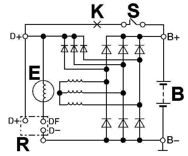
| Ignition off - static picture |

| Component description |
| B | Battery |
| S | (Ignition) switch |
| E | Exciter windings |
| R | Voltage regulator |
| K | Control lamp |
Before you go on scrolling have a look at the basic scheme. The exciter winding rotates and induces current in the three strands, which are connected to the battery through the plus- and minus performance diodes
and
the terminals B+ and B-. B+ is again connected through the (classical) ignition switch S and the (also classical) control lamp K connected with D+. D+ is supplied by three (smaller) exciter diodes, which are switched
parallel to the plus diodes. D+ forms the feedback and current supply to the regulator, which controls the exciter windings through DF.

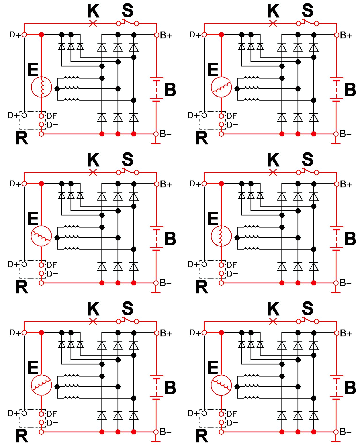
| Pre-exciter current circuit (start) - animation |
We now switch the ingnition on and start the engine. At starting RPM not enough voltage would be generated, because the excitation through the rotor would be too low. This would have to get going through the
remaining magnetism, which is deliberately kept low in the manufacturing/conception, to allow the complete regulation range, right up to almost zero-regulation in normal operation. As you can see in the red-coloured
circuit, the power for the exciter windings when starting, comes from the battery (external supply).

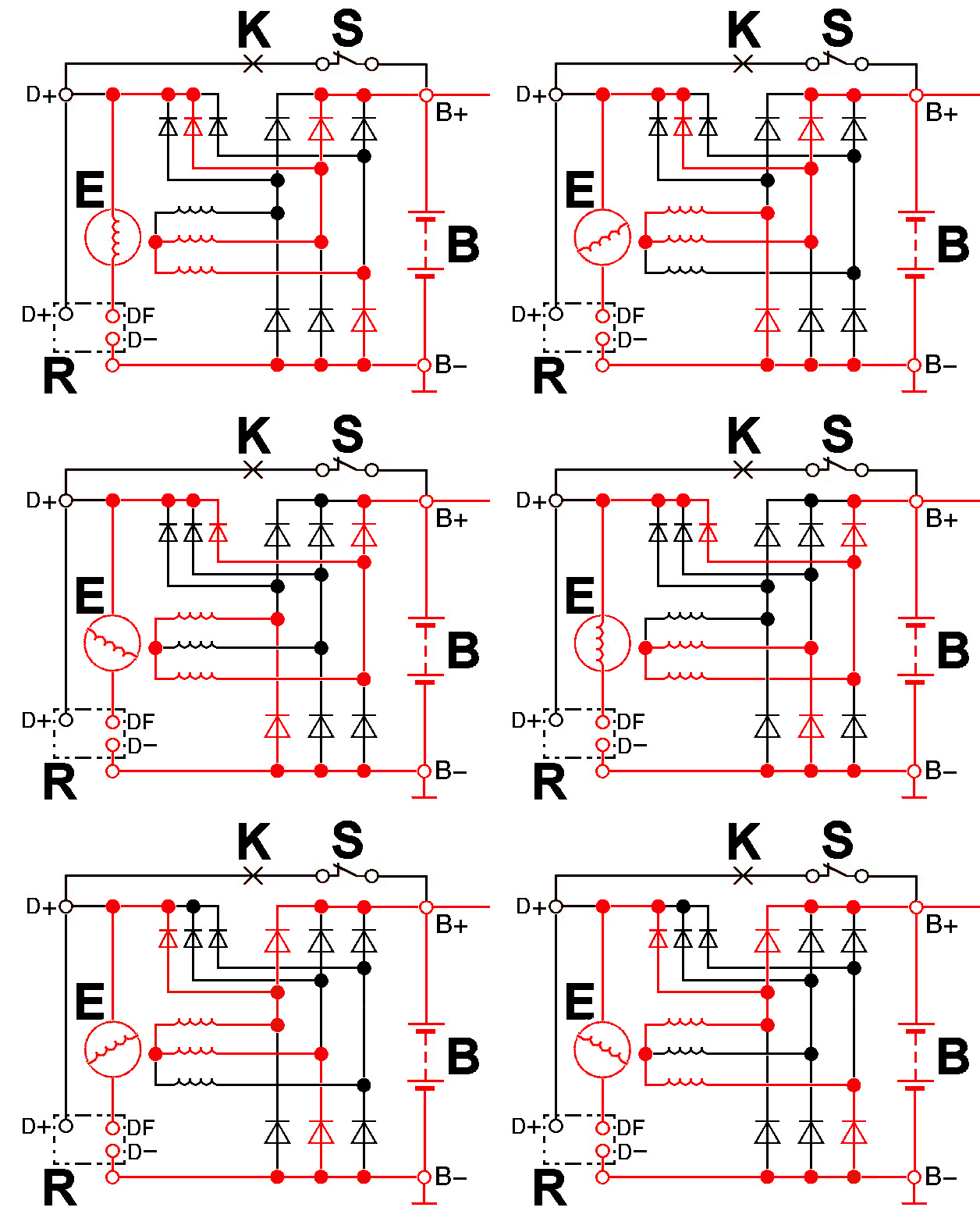
| Exciter current circuit (engine running) - animation |
An exciter current circuit we have, when the voltage exceeds the 0,7 V at the exiter diodes plus the 0,7 V at the power diodes. One may assume, somewhere between starting and idling. In this situation, the exciter
diodes
deliver sufficient voltage for excitation, however, for the transition to the performance diodes to charge the battery, it is not yet enough. It can be nicely seen here, how one of the strands U, V and W for two 60°
angles, always gains the upper-hand in the delivery of plus-current. Of course, the same thing counts for the minus-side. Between each 60° phase, the red line alternates between the plus- and the minus diodes.

| Consumer current circuit (charging) - animation |
At this point, it is sufficient to charge the battery or to send current to the consumers. This goes on, until the regulator R, due to the exceeding of the set voltage, periodically switches off, to limit this. 10/16
|
|