|
 Battery - Alternator - Starter Battery - Alternator - Starter

How it works
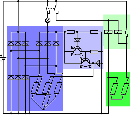
This circuit diagram shows the alternator (dark blue) with it's voltage regulator (light blue). Next to it, on the right, the circuit diagram of the starter (dark green) with it's solenoid switch (light green) is shown. When
the ignition switch (above) is in the position 'ignition on', the plus-pole of the charging control light is switched. This is connected to the minus-pole through the rotor coil in the alternator. It serves as a pre-resistance
and only goes out the moment the engine starts. If it is driven by the engine, then both terminals of the control lamp are given plus current and the lamp goes out. Because of their low current consumption, modern
LED-lamps have a parallel-switched resistance.
In the solenoid (lightgreen) a large cross-section is switched on and off by two electromagnets. How the relay actually switches these large cross-sections, 16 mm² and more, is shown in the small diagram
above this paragraph. The pull-in winding, like the charge control lamp, receives plus current from the ignition switch and minus from the serially switched armature- and stator winding of the starter. This condition
remains as long as the starter is not switched. The pull-in winding thus, switches itself off. All that then remains, is the holding coil. As the name suggests, it is strong enough to hold the large contact in the switching
position. 02/12
| Charging control lamp |
| Between 15 and D+ |
|
|