
|
Electronics 5
| 1 | Earth |
| 2 | Trigger |
| 3 | Output |
| 4 | Reset |
| 5 | Controlling tension |
| 6 | Switching threshhold |
| 7 | Discharge |
| 8 | Supply |
The NE 555 is an interesting component, indeed, one belonging to the digital electronics. It is a so-called timer. In picture 2, shown here with a red border, you can see one possible circuit with this timer. It generates
rectangular impulses, which can be determined by using either one or two resistors and a condenser. The impulses are generated through the charging and discharging of the condenser.
If you're now asking yourself, where the timer is needed, the answer can only be: almost anywhere. You may be thinking of the windscreen wiper interval switching, which is correct. Indeed, have you ever heard of the
'pulse-width modulation'? This here would be one, all you would need to do is to vary the external components. However, this is a part of the
digital electronics.
| You can also read about the NE 555 timer here. |
What we're interested in, is the way that an operational amplifier works, of which there are two installed. Perhaps we should start with a general description: What comes out, is different from that which was sent in. In
the case of a genuine amplification, the output voltage e.g., would be higher than the input. We will be shown, that there's much more to it than just that.
We'll use the amplification, firstly to explain the connections of an operational amplifier. It has two inputs and one output. The voltage between the two inputs is amplified, This is the reason why the one with the higher
voltage is described as plus- and the one with the lower voltage as minus. Later on we will also describe them as being 'non-inverting' and 'inverting'.
Assuming large amplification factors, because the operational amplifier contains several transistors, at least then when no strain is applied (idling voltage). 10.000 is one factor, which however, can vary greatly from
one amplifier to the other. So, you already know about three of the connections, in addition, there are also the fourth and fifth, for the voltage supply. Up to now, using a triangle as the basic symbol it is still very clearly
defined, because none of the contacts is connected with another.
Thus e.g., the output can be connected with the higher voltage-input (plus-input), which then leads to positive feedback. Thus one generates higher voltage, which is then again laid onto the input. We won't deal any
further with the consequences and limitations of this circuit because the opposite of this is by far, the more important.
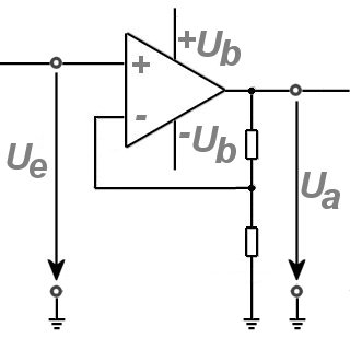
| Ue | Input voltage |
| Ua | Output voltage |
| Ub | Power supply voltage |
This would then be the negative feedback, where a part of the output voltage is laid onto the negative input. Should the input voltage then undulate, which is almost the norm anyway, it is most reduced at exactly the point
where it was highest before. That would be the first real regulation process and it is understandable, why the first operational amplifiers (tube technology), were used, unfortunately, at the beginning of the second world
war, to improve the regulation of the artillery guns.
|
|